
The Reality of Beginner Kit Potentiometers
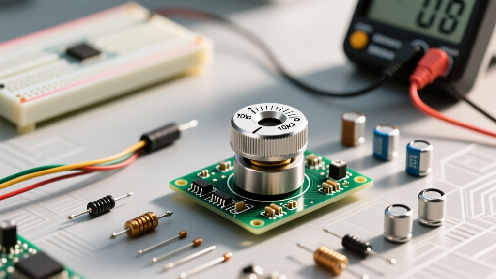
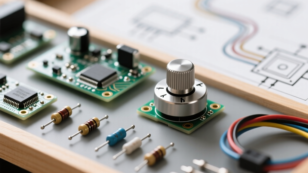
If you have just unboxed an Arduino, ESP32, or Raspberry Pi starter kit from brands like Elegoo, Rexqualis, or Vilros, you are likely holding a small bag of blue or black rotary components. These are potentiometers (often called "pots"), and they are the backbone of analog input prototyping. However, beginner kits are famous for including budget-friendly, carbon-track potentiometers that can suffer from wide manufacturing tolerances, stiff wipers, or even dead-on-arrival (DOA) internal tracks.
Before you wire a B10K potentiometer into a voltage divider circuit and spend hours debugging why your microcontroller is reading erratic analog values, you need to verify the component. Learning how to measure resistance of a potentiometer with a digital multimeter (DMM) is a foundational skill that separates frustrated beginners from confident hardware prototypers.
Setting Up Your Multimeter for Resistance
To measure resistance, your multimeter must be set to the Ohms (Ω) setting. If you are using a manual-ranging multimeter common in beginner kits, you must select a range higher than the expected resistance of your potentiometer.
- For a 10KΩ (B10K) pot: Set the dial to the 20KΩ or 200KΩ range.
- For a 50KΩ (B50K) pot: Set the dial to the 200KΩ range.
- For a 100KΩ (B100K) pot: Set the dial to the 200KΩ or 2MΩ range.
Ensure your test leads are plugged into the correct ports: the black lead into COM and the red lead into the port labeled Ω / V / mA. Never attempt to measure resistance while the potentiometer is connected to a live, powered breadboard circuit; the external voltage will skew your readings and could blow the internal fuse of your multimeter. For a deeper dive on DMM safety and setup, refer to SparkFun's comprehensive multimeter guide.
Anatomy of a Breadboard Potentiometer
Most beginner kits include breadboard-friendly potentiometers with three inline pins. Understanding the pinout is critical before you place your probes.
- Pin 1 (CCW / Ground): Connected to one end of the internal resistive carbon track.
- Pin 2 (Wiper / Signal): The middle pin, connected to the physical metal arm that sweeps across the carbon track. This is your variable output.
- Pin 3 (CW / VCC): Connected to the opposite end of the resistive track.
Pro-Tip: If you flip the potentiometer over and look at the solder lugs on the back, Pin 1 is typically on the left, Pin 2 (wiper) is in the center, and Pin 3 is on the right, assuming the shaft is facing away from you.
Step 1: Measuring Total Nominal Resistance
The first test verifies the total fixed resistance of the component. This tells you if the carbon track is intact and if the manufacturer's tolerance is within acceptable limits.
- Turn the potentiometer shaft to any position (the wiper position does not matter for this test).
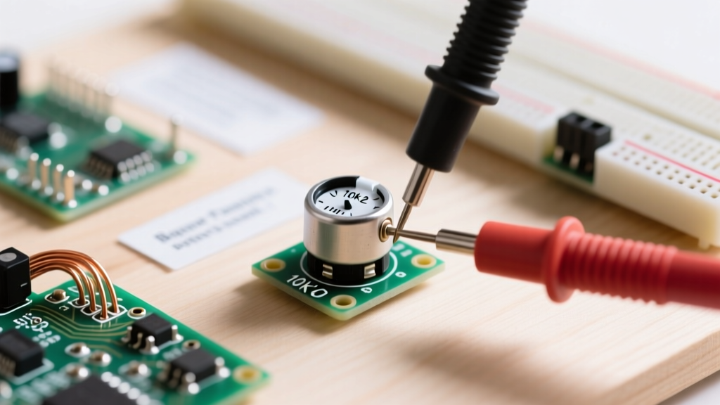
- Place your red probe on Pin 1 and your black probe on Pin 3 (the two outer pins).
- Read the display.
If you are testing a B10K potentiometer, the display should read close to 10.00 KΩ. However, budget kit components usually carry a ±20% tolerance. This means a reading anywhere between 8.0 KΩ and 12.0 KΩ is completely normal and safe to use in standard microcontroller projects. If your multimeter reads "OL" (Over Limit) or infinity, the internal carbon track is snapped, and the component belongs in the trash bin.
Step 2: Sweeping the Wiper (Dynamic Testing)
Now we test the variable nature of the component. This step reveals "dead spots" or oxidized sections on the carbon track that cause jumpy analog readings in Arduino projects.
- Leave the black probe on Pin 1.
- Move the red probe to Pin 2 (the center wiper).
- Slowly rotate the shaft from the fully counter-clockwise (CCW) position to the fully clockwise (CW) position.
As you turn the shaft, the resistance value on your multimeter should climb smoothly from near 0Ω up to the total nominal resistance you measured in Step 1. According to Electronics Tutorials, the wiper creates a variable voltage divider; if the physical carbon track has microscopic gaps, your multimeter will display sudden, erratic jumps in resistance. If you observe the numbers skipping wildly (e.g., jumping from 2KΩ straight to 7KΩ with a slight turn), that potentiometer will cause severe jitter in your analogRead() code.
Understanding Taper: Why Your LED Fades Weirdly
Beginners often measure resistance correctly but are confused when an LED connected to the pot fades too quickly or too slowly. This is dictated by the taper, indicated by the letter printed on the back of the casing.
- Linear Taper (B): Printed as B10K or B50K. The resistance changes at a constant, even rate relative to the shaft angle. At 50% rotation, the resistance between Pin 1 and Pin 2 is exactly 50% of the total. This is what you need for microcontroller analog inputs and LED dimming.
- Logarithmic / Audio Taper (A): Printed as A10K or A50K. The resistance changes slowly at first, then rapidly. This mimics human hearing perception and is used in audio volume controls, but it will make your Arduino sensor projects behave unpredictably.
Always verify the letter prefix on your kit components. If your kit only includes "A" taper pots, you will need to apply software compensation curves in your C++ or Python code to linearize the input data.
Troubleshooting Common Kit Potentiometer Failures
Even brand-new components from beginner kits can exhibit mechanical flaws. Here is how to diagnose them using your multimeter:
The "Scratchy" or Jumpy Reading
Symptom: The multimeter flickers rapidly between two values when the shaft is held perfectly still. Cause: Carbon dust accumulation or oxidation on the wiper contact point. Fix: Rotate the knob back and forth rapidly from end to end about 20 times. This friction can sometimes wipe away surface oxidation. For persistent issues, a drop of DeoxIT contact cleaner into the casing slot can save the component.
The "Dead Zone"
Symptom: The resistance stays flat at 0Ω or stays flat at maximum resistance for a large portion of the knob's rotation. Cause: The metal wiper arm is bent and has lost physical tension against the carbon track. Fix: Unfortunately, budget pots are usually sealed with metal crimps. Prying them open to bend the wiper arm usually results in the carbon track shattering. Replace the component.
Breadboard Contact Resistance
Symptom: Your multimeter reads the correct value when probing the pins directly, but your Arduino reads garbage data. Cause: The thin, stamped-metal pins on kit potentiometers are often slightly narrower than standard IC pins, leading to poor friction inside cheap breadboard clips. Fix: Solder short lengths of 22AWG solid-core wire to the potentiometer pins before inserting them into the breadboard to ensure a rock-solid electrical connection.
Reference Table: B10K Linear Potentiometer Sweep
Use this table as a benchmark when testing a standard 10KΩ linear (B-taper) potentiometer from your kit. Minor deviations of ±5% are normal due to multimeter lead resistance and carbon track tolerances.
| Shaft Position (Approx.) | Pin 1 to Pin 2 (Wiper) | Pin 2 to Pin 3 (Wiper) | Sum of Both Readings |
|---|---|---|---|
| 0% (Fully CCW) | ~0 Ω | ~10,000 Ω | 10,000 Ω |
| 25% Rotation | ~2,500 Ω | ~7,500 Ω | 10,000 Ω |
| 50% (Center Detent) | ~5,000 Ω | ~5,000 Ω | 10,000 Ω |
| 75% Rotation | ~7,500 Ω | ~2,500 Ω | 10,000 Ω |
| 100% (Fully CW) | ~10,000 Ω | ~0 Ω | 10,000 Ω |
Final Thoughts for the Prototyping Workbench
Mastering how to measure resistance of a potentiometer takes less than two minutes, but it saves hours of frustrating software debugging. By verifying the total resistance, sweeping the wiper for dead spots, and confirming the taper type, you ensure that the analog inputs on your microcontroller receive clean, predictable voltage data. For further reading on how these variable resistors manipulate current flow in DC circuits, review the potentiometer chapter in the All About Circuits DC textbook. Keep your multimeter handy, trust your measurements, and happy prototyping!