
The Anatomy of an NPN Junction: Beyond the Schematic Symbol
When engineers and hobbyists refer to an NPN junction, they are typically shorthand-referencing the NPN Bipolar Junction Transistor (BJT). However, to truly master circuit design, you must understand that an NPN transistor is not a single component, but rather a sandwich of two distinct P-N junctions: the Base-Emitter (BE) junction and the Base-Collector (BC) junction. According to Georgia State University's HyperPhysics, the magic of the NPN BJT relies on the physical proximity of these two junctions and the deliberate doping gradients within the silicon die.
The Emitter is heavily doped with N-type impurities to flood the Base with electrons. The Base is incredibly thin and lightly doped with P-type material, allowing most electrons to diffuse straight through it. The Collector is moderately doped and physically larger to dissipate heat. In any practical circuit application tutorial, manipulating the depletion regions of these two internal NPN junctions is the key to controlling current flow.
Biasing the Base-Emitter Junction: The 0.7V Threshold
The Base-Emitter junction behaves exactly like a standard silicon diode. To turn the transistor "on," you must forward-bias this junction. For standard silicon NPN transistors like the ubiquitous 2N3904 or BC547, this requires a forward voltage drop ($V_{BE}$) of approximately 0.65V to 0.7V. If your base drive voltage is below this threshold, the junction remains in cutoff, and no collector current will flow.
Calculating the Base Resistor for Hard Saturation
When using an NPN transistor as a switch, your goal is to drive the transistor into hard saturation. In saturation, both the BE and BC junctions are forward-biased, and the voltage drop across the Collector-Emitter ($V_{CE(sat)}$) drops to roughly 0.2V, minimizing power dissipation.
A common beginner mistake is using the datasheet's $h_{FE}$ (DC current gain) to calculate the base resistor. The $h_{FE}$ is specified for the active (linear) region. To guarantee saturation in the real world, you must use a "forced beta"—typically dividing the $h_{FE}$ by 10.
- Target Collector Current ($I_C$): 50mA (e.g., a small 12V relay coil)
- Forced Beta: 10
- Required Base Current ($I_B$): $I_C / 10 = 5mA$
- MCU GPIO Voltage ($V_{GPIO}$): 3.3V (e.g., ESP32)
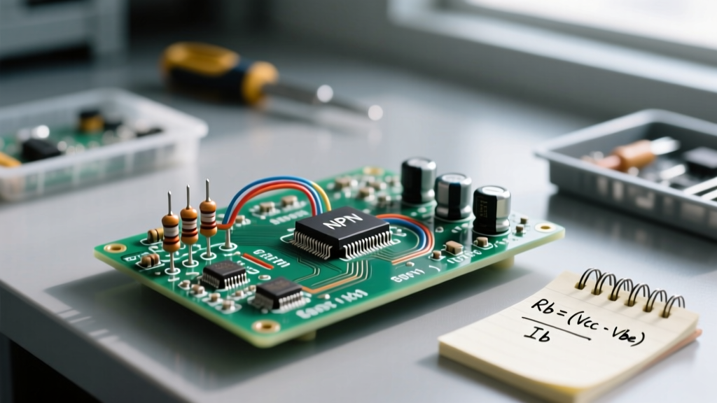
- Base Resistor ($R_B$): $(V_{GPIO} - V_{BE}) / I_B = (3.3V - 0.7V) / 0.005A = 520\Omega$
In practice, you would select the next lowest standard E12 resistor value, which is 470Ω, ensuring a robust 5.5mA base drive and a rock-solid NPN junction saturation.
Comparing Common NPN Transistors for Prototyping
Not all NPN junctions are created equal. The physical geometry and doping profiles dictate the transistor's maximum current, switching speed, and voltage thresholds. Below is a comparison of three workhorse NPN transistors you will encounter on the prototyping bench.
| Part Number | Max $I_C$ | Max $V_{CEO}$ | Typical $h_{FE}$ | Best Application |
|---|---|---|---|---|
| 2N3904 | 200mA | 40V | 100 - 300 | Low-power switching, logic level shifting |
| 2N2222A | 800mA | 40V | 100 - 300 | Medium loads, motor drivers, higher current relays |
| TIP120 (Darlington) | 5A | 60V | 1000+ | High-current loads, PWM LED dimming, solenoids |
Note: The TIP120 is a Darlington pair, meaning it contains two NPN junctions in series. Consequently, its $V_{BE}$ threshold is roughly 1.4V, and its $V_{CE(sat)}$ is much higher (around 1.0V to 2.0V), requiring a heatsink even at moderate currents. Consult the ON Semiconductor 2N3904 Datasheet for exact thermal derating curves.
Application 1: Low-Side Switching with Flyback Protection
The most reliable way to switch an inductive load (like a relay, solenoid, or DC motor) is using an NPN transistor in a low-side configuration. The load is connected between the positive supply and the Collector, while the Emitter is tied directly to ground.
The Flyback Diode Imperative
When the NPN junction is abruptly turned off by removing the base drive, the magnetic field in the inductive load collapses. This induces a massive reverse voltage spike (often hundreds of volts) that will instantly punch through the Base-Collector junction, destroying the silicon die. You must place a flyback diode (such as a 1N4148 for small signal relays or a 1N4007 for larger motors) in reverse bias across the load. The cathode connects to the positive supply, and the anode connects to the Collector. This provides a safe recirculation path for the inductive kickback current.
Application 2: Common-Emitter Amplifier Design
While switching utilizes the NPN junction in saturation and cutoff, amplification requires biasing the transistor in the active region. In a common-emitter amplifier, the BE junction is forward-biased, and the BC junction is reverse-biased.
Setting the Q-Point for Maximum Symmetrical Swing
To prevent signal clipping, the Quiescent Point (Q-point) must be centered on the DC load line. Let's design a stable voltage-divider bias network for an audio pre-amplifier stage using a BC547.
- Supply ($V_{CC}$): 12V
- Target Collector Current ($I_{CQ}$): 2mA
- Target Collector-Emitter Voltage ($V_{CEQ}$): 6V (Half of $V_{CC}$ for maximum symmetrical swing)
First, we calculate the Collector Resistor ($R_C$):
$R_C = (V_{CC} - V_{CEQ}) / I_{CQ} = (12V - 6V) / 0.002A = 3000\Omega$. We will use a standard 3.3kΩ resistor.
Next, to stabilize the NPN junction against thermal drift, we add an Emitter Resistor ($R_E$). A good rule of thumb is to drop about 10% of $V_{CC}$ across $R_E$.
$V_E = 1.2V$. Therefore, $R_E = 1.2V / 0.002A = 600\Omega$. We will use a standard 680Ω resistor.
Now, we calculate the Base voltage divider ($R_1$ and $R_2$). The Base voltage ($V_B$) must be $V_E + V_{BE} = 1.2V + 0.7V = 1.9V$. To make the bias "stiff" and independent of the transistor's highly variable $h_{FE}$, the current through the divider should be at least 10 times the base current ($I_B \approx 20\mu A$, so divider current $\approx 200\mu A$).
$R_2 = V_B / 200\mu A = 1.9V / 0.0002A = 9500\Omega$ (Use 10kΩ).
$R_1 = (V_{CC} - V_B) / 200\mu A = (12V - 1.9V) / 0.0002A = 50500\Omega$ (Use 47kΩ).
This specific component selection ensures the NPN junction remains perfectly in the active region, even if the ambient temperature shifts or you swap the BC547 for another unit with a completely different manufacturing gain batch.
NPN Junction Failure Modes and Thermal Runaway
Understanding how an NPN junction fails is just as critical as knowing how to bias it. Silicon junctions are highly temperature-dependent.
The -2mV/°C Rule: For every 1°C increase in junction temperature, the $V_{BE}$ required to maintain a specific collector current drops by approximately 2mV. If a circuit lacks proper emitter degeneration (an $R_E$ resistor), this temperature rise causes the transistor to draw more current, which generates more heat, which drops the $V_{BE}$ further. This positive feedback loop is known as thermal runaway and will result in catastrophic junction melting.
Safe Operating Area (SOA) and Secondary Breakdown
When operating NPN transistors at high voltages and high currents simultaneously (such as in linear power supplies or audio output stages), you must respect the Safe Operating Area (SOA) graph in the datasheet. Pushing the NPN junction beyond the SOA limit triggers secondary breakdown. Unlike thermal runaway, which takes seconds or minutes to destroy a part, secondary breakdown occurs in microseconds. It happens when current crowding creates microscopic "hot spots" on the silicon die, instantly shorting the Collector to the Emitter. Always use adequate heatsinking and current-limiting resistors when operating near the transistor's maximum $V_{CEO}$ and $I_C$ limits.