
The Anatomy of an I2C OLED Display Driver
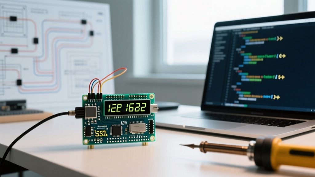
When integrating a display OLED I2C module into a microcontroller project, the hardware is only half the battle. The ubiquitous 0.96-inch 128x64 OLED, driven by the SSD1306 controller, relies on a highly specific communication protocol. Unlike SPI, which uses a dedicated Data/Command (D/C) pin to tell the display whether incoming bytes are pixel data or configuration commands, I2C embeds this distinction into a control byte. Every I2C transmission to the OLED must begin with a control byte: 0x00 for commands and 0x40 for GDDRAM (Graphics Display Data RAM) pixel data.
Understanding this underlying architecture is critical when selecting a driver library. A poorly optimized library will waste precious CPU cycles and SRAM buffering data, while a highly optimized driver can push the I2C bus to its physical limits. In this guide, we dissect the most popular Arduino and ESP-IDF libraries for I2C OLEDs, evaluating their memory footprints, rendering paradigms, and hardware quirks.
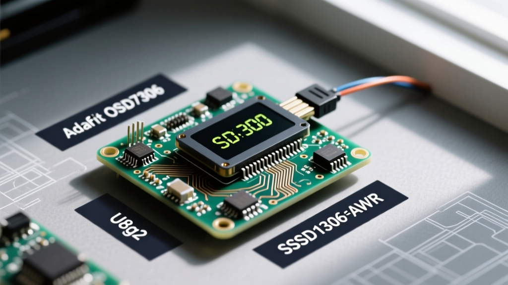
Memory Footprint Showdown: Adafruit vs. U8g2 vs. SSD1306Ascii
The most severe bottleneck when driving a 128x64 display OLED I2C module on 8-bit AVRs (like the ATmega328P) is SRAM. A full-screen frame buffer requires exactly 1,024 bytes (128 * 64 / 8). On a microcontroller with only 2KB of SRAM, a single full buffer consumes 50% of your available memory, leaving little room for network stacks or sensor arrays.
Below is a comparative analysis of the top libraries based on an ATmega328P compilation target:
| Library | Flash Usage (Approx) | RAM Buffer Mode | Max FPS (I2C 400kHz) | Best Use Case |
|---|---|---|---|---|
| Adafruit_SSD1306 | ~6.5 KB | Full (1024 bytes) | ~18 FPS | Rapid prototyping, ESP32/RP2040 |
| U8g2 | ~12 KB to 25 KB | Page or Full | ~24 FPS (Page Mode) | Complex UIs, localized fonts, AVR/ESP |
| SSD1306Ascii | ~3.2 KB | None (Direct Write) | N/A (Text Only) | Strict memory limits, data logging |
| LVGL (via I2C) | ~60+ KB | Partial/Full (Custom) | ~12 FPS | High-end ESP32/STM32 touch GUIs |
Deep Dive: U8g2's Page Buffer vs. Full Buffer Mode
The U8g2 Library Repository remains the gold standard for memory-constrained environments. Its genius lies in the "Page Buffer" mode. Instead of allocating 1,024 bytes, U8g2 allocates a single "page" (128x8 pixels, requiring only 128 bytes). The rendering loop executes your drawing commands multiple times, shifting the buffer window down the screen with each pass.
u8g2.firstPage();
do {
  u8g2.drawStr(0, 22, "ElectricalFlux I2C Guide");
  u8g2.drawCircle(64, 32, 20);
} while (u8g2.nextPage());
While this saves 896 bytes of SRAM, it forces the MCU to re-calculate vector graphics and font glyphs up to eight times per frame. On an ATmega328P, this CPU overhead is negligible compared to the time spent transmitting data over the 400kHz I2C bus. However, on faster MCUs like the ESP32, the CPU bottleneck becomes apparent, making Full Buffer mode (u8g2.setDisplayRotation() with _F_ constructors) a better choice if RAM permits.
Resolving the 0x3C vs 0x3D I2C Address Conflict
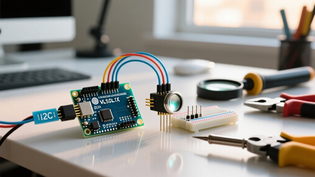
A frequent stumbling block for engineers wiring up a display OLED I2C module is the hardcoded I2C address. Most 0.96-inch modules default to 0x3C. However, the SSD1306 datasheet specifies that the SA0 (Slave Address Select) pin can toggle the address to 0x3D.
On many budget breakout boards, the SA0 pin is tied to ground via a 0-ohm resistor, or left floating with an internal pull-up. If you are integrating two OLEDs onto the same I2C bus for a dual-screen telemetry dashboard, you must physically locate the SA0 resistor pad on the PCB, desolder the bridge, and move it to the alternate pad. Software address swapping is impossible on standard SSD1306 I2C modules without hardware modification.
Hardware Pull-up Resistor Failures on Clone Boards
If your I2C bus scanner fails to detect the OLED, or if the display exhibits random flickering and dropped frames, the culprit is rarely the library. According to the Adafruit Monochrome OLED Breakouts Guide, proper I2C communication requires 4.7kΩ pull-up resistors on the SDA and SCL lines.
Many mass-produced clone boards omit these resistors to save fractions of a cent, relying entirely on the microcontroller's internal weak pull-ups (usually 20kΩ to 50kΩ). At standard 100kHz I2C speeds, this might barely work. But when you push the bus to 400kHz (Fast Mode) to increase frame rates, the RC time constant of the bus capacitance combined with weak pull-ups results in skewed signal edges. The SSD1306 misinterprets the corrupted clock pulses, leading to display tearing or complete bus lockups.
Expert Hardware Hack: Always add external 4.7kΩ pull-up resistors to the SDA and SCL lines on your breadboard or custom PCB when using cheap OLED modules. If you are running the I2C bus at 800kHz (Fast Mode Plus) on an ESP32, drop the pull-ups to 2.2kΩ to ensure sharp signal rise times.
Frame Rate Optimization: Pushing Past 30 FPS on I2C
The I2C protocol is inherently slower than SPI. A standard 1024-byte frame buffer transmitted at 400kHz takes approximately 20.4 milliseconds, theoretically capping your frame rate at around 48 FPS (excluding command overhead and MCU processing time). To achieve smooth animations on a display OLED I2C setup, you must optimize the bus clock and the GDDRAM update window.
- Overclocking the Wire Library: On AVR and ESP32 architectures, you can safely override the default I2C clock. Insert
Wire.setClock(800000L);immediately afterWire.begin(). The SSD1306 controller can reliably handle 800kHz, effectively halving your transmission time. - Partial Screen Updates: If your UI only updates a small graph or a single text variable, do not redraw the entire GDDRAM. Libraries like SSD1306Ascii Lightweight Driver allow you to target specific character rows and columns, transmitting only the bytes that have changed. This reduces I2C payload from 1024 bytes to as little as 16 bytes per update.
- Adjusting the MUX Ratio: For 128x32 OLED variants, ensure your initialization sequence sets the Multiplex Ratio (Command
0xA8) to0x1F(31) rather than0x3F(63). Sending data to unpopulated GDDRAM rows wastes I2C bandwidth.
Migrating from SPI to I2C: What You Lose
While the 4-pin I2C interface (VCC, GND, SCL, SDA) is vastly easier to wire than the 7-pin SPI alternative, developers must accept specific trade-offs. SPI allows for direct memory addressing and vastly superior bandwidth (easily exceeding 10 MHz), enabling high-framerate video playback or complex greyscale dithering. I2C is strictly limited by its open-drain architecture and bus capacitance. If your project requires smooth, 60 FPS scrolling marquee text or dynamic bitmap animations, the display OLED I2C protocol will bottleneck your design. In those scenarios, migrating to a hardware SPI driver using the U8g2 _HW_SPI_ constructors is mandatory.
Final Verdict: Choosing Your Driver Stack
Selecting the right library for your I2C OLED depends entirely on your target silicon and project scope:
- For ATmega328P / Arduino Uno: Use SSD1306Ascii if you only need text and telemetry. Use U8g2 (Page Mode) if you need graphics, charts, and custom fonts without crashing the SRAM.
- For ESP32 / RP2040: Use Adafruit_SSD1306 or U8g2 (Full Buffer). These MCUs have hundreds of kilobytes of RAM; the 1KB buffer is trivial, and you benefit from the simpler, single-pass drawing APIs.
- For Complex Touch/GUI Dashboards: Use LVGL with a custom I2C display driver callback, but ensure you are using an ESP32-S3 or similar high-performance chip to handle the LVGL tick and render cycles over the slower I2C bus.
By matching the library's memory paradigm to your MCU's architecture, and ensuring your physical I2C bus is properly terminated with pull-up resistors, your display OLED I2C integration will be robust, flicker-free, and highly optimized.