
The Anatomy of a Current Sensor Datasheet
When integrating an arduino current sensor into your microcontroller project, copying and pasting a GitHub library is rarely enough for precision measurements. To achieve true reliability, you must decode the manufacturer's datasheet. Whether you are measuring the milliamp sleep current of an ESP32 or the 15-amp draw of a DC motor, the datasheet holds the keys to accuracy, bandwidth, and failure prevention.
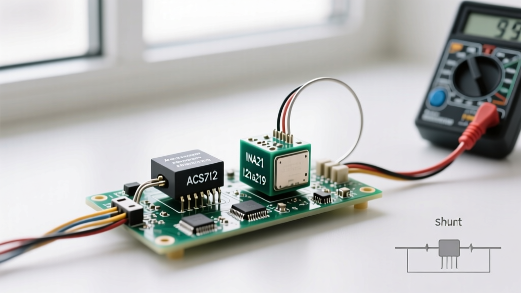
In this guide, we dissect the two most ubiquitous architectures in the DIY and prototyping space: the Hall-effect based Allegro ACS712 and the shunt-based Texas Instruments INA219. We will translate dense silicon specifications into actionable wiring and coding strategies.
Hall-Effect vs. Shunt Monitors: Silicon Showdown
Before diving into specific part numbers, it is critical to understand the fundamental divergence in how these ICs measure electron flow. Hall-effect sensors measure the magnetic field generated by current, providing galvanic isolation. Shunt monitors measure the voltage drop across a known resistance, requiring direct electrical contact but offering vastly superior precision at low currents.
Allegro ACS712: The Analog Hall-Effect Workhorse
The ACS712 is a staple in the Arduino ecosystem due to its low cost and simple analog output. However, the datasheet reveals specific quirks that trip up beginners. Let us focus on the widely used ACS712-20A variant.
- Sensitivity: The datasheet specifies a nominal sensitivity of 100 mV/A. This means for every 1 Ampere of current, the output voltage shifts by 100 millivolts.
- Offset Voltage ($V_{IOUT}$): Powered at 5.0V, the quiescent output voltage is exactly half of $V_{CC}$, or 2.5V. At 0A, your Arduino analog pin should read 2.5V.
- Bandwidth and Noise: The IC boasts an 80 kHz bandwidth. While great for switching power supplies, this wide bandwidth admits high-frequency noise. The datasheet lists a total output noise of roughly 11 mV RMS. On a standard 10-bit Arduino Uno ADC (where 1 LSB $\approx$ 4.88 mV), this noise translates to 2 to 3 steps of jitter. Datasheet Fix: Use the FILTER pin. By tying a capacitor between the FILTER pin and GND, you engage an internal low-pass filter to tame this jitter.
According to the Allegro MicroSystems ACS712 documentation, the internal filter resistor is approximately 1.1 k$\Omega$. To set a cutoff frequency of 1 kHz, you would need a capacitor of roughly 145 nF (a standard 0.1 $\mu$F ceramic capacitor works perfectly).
Texas Instruments INA219: The I2C Shunt Powerhouse
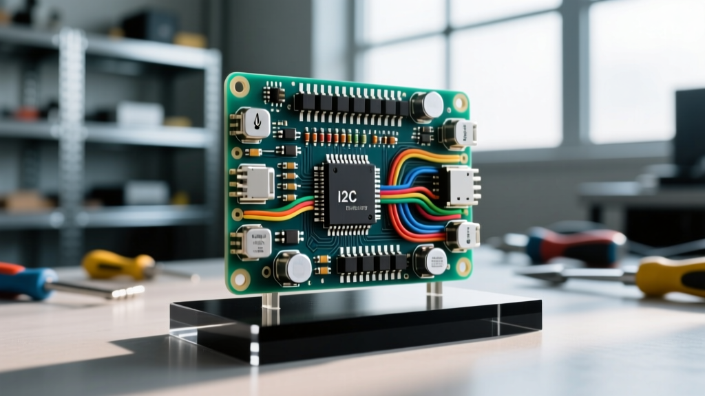
For high-side current sensing and power monitoring, the INA219 is unmatched in the prototyping world. It features an I2C interface, a 12-bit ADC, and a programmable gain amplifier (PGA).
The most crucial section of the Texas Instruments INA219 Datasheet is the Calibration Register math. Unlike the ACS712, the INA219 does not output raw voltage; it calculates current based on an internal shunt voltage measurement and a calibration constant you must provide via I2C.
Critical Datasheet Warning: The INA219 ADC can only measure a maximum shunt voltage of 320 mV. If your load draws 10A through a 0.1 $\Omega$ shunt resistor, the voltage drop will be 1.0V ($10A \times 0.1\Omega$). This exceeds the 320 mV limit, saturating the ADC and resulting in completely invalid readings. Always calculate your maximum expected current against your shunt resistance first.
To optimize the 12-bit ADC resolution, the datasheet recommends selecting a shunt resistor that drops close to, but just under, 320 mV at your maximum expected current. For a 3A maximum load, a 0.1 $\Omega$ shunt yields a 300 mV drop, perfectly utilizing the ADC's dynamic range.
Translating Datasheet Specs to Arduino Code
Let us bridge the gap between the silicon specs and your C++ sketch.
ACS712 Analog Math
To convert the 10-bit ADC reading (0-1023) back to Amperes, you must reverse the sensitivity formula:
float voltage = (analogRead(A0) * 5.0) / 1024.0;
float current = (voltage - 2.5) / 0.100; // 0.100 is 100mV/A sensitivity
Pro-Tip: The datasheet notes a "Ratiometric" output. If your Arduino's 5V rail sags to 4.8V under load, the 2.5V offset also sags, introducing massive errors. Always measure the actual $V_{CC}$ using the Arduino's internal reference if precision is required.
INA219 Calibration Register
The INA219 datasheet provides a specific formula for the Calibration Register (CAL):
$CAL = \text{trunc}(0.04096 / (\text{Current\_LSB} \times R_{SHUNT}))$
If you use a 0.1 $\Omega$ shunt and want a maximum current of 3.2A, your Current_LSB is $3.2 / 32768 \approx 0.0000976$ A. Plugging this into the formula yields a CAL value of 4096. Writing this to register 0x05 via I2C configures the chip to output perfectly scaled milliamp readings in the Current Register.
Hardware Failure Modes and Datasheet Warnings
Datasheets are essentially autopsies of how the chip was tested to destruction. Ignoring the "Absolute Maximum Ratings" table is the fastest way to kill your arduino current sensor.
- Inductive Kickback (ACS712): While the ACS712 provides 2.1 kVRMS galvanic isolation between the IP+ / IP- pins and the signal pins, the signal pins themselves are not immune to ground loops. If the high-current load shares a ground return path with the Arduino, voltage spikes can exceed the 6V absolute maximum on the $V_{OUT}$ pin, frying the op-amp.
- Common-Mode Voltage Limits (INA219): The INA219 is a high-side monitor. The datasheet specifies an absolute maximum common-mode bus voltage of 26V. If you attempt to monitor a 36V e-bike battery, the internal ESD protection diodes will avalanche, permanently shorting the I2C bus and potentially taking your microcontroller down with it. For higher voltages, consider high-voltage alternatives like the Analog Devices LTC6101 high-side current sense amplifier.
- Shunt Power Dissipation: A datasheet will list the shunt resistor's power rating, but hobbyist modules often undersize it. A 0.1 $\Omega$ SMD resistor pushing 3A dissipates $I^2R = 9 \times 0.1 = 0.9W$. If the module uses a standard 1/4W (0.25W) resistor, it will overheat, drift in resistance, and ruin your calibration.
Final Selection Matrix for Your Next Build
Use this matrix to select the right architecture based on your project's electrical profile:
| Specification | Allegro ACS712 (20A) | Texas Instruments INA219 |
|---|---|---|
| Measurement Type | Hall-Effect (Isolated) | Shunt Monitor (High-Side) |
| Interface | Analog Voltage (0.5V - 4.5V) | I2C Digital |
| Zero-Current Accuracy | Poor ($\pm$20mA offset drift) | Excellent ($\pm$10$\mu$V offset) |
| Max Bus Voltage | N/A (Galvanically Isolated) | 26V |
| Best Use Case | AC Mains, High-Current DC Motors | Battery Monitoring, Sleep Current |
| Typical Module Cost | $2.50 - $4.00 | $3.00 - $5.50 |
By reading beyond the first page of the datasheet, you transform generic Arduino modules into precision laboratory instruments. Always respect the silicon limits, calculate your burden voltages, and filter your analog signals.