
The Anatomy of a Perfect Electrical Solder Joint
Understanding how to solder electrical connections reliably requires more than just melting metal; it demands a fundamental grasp of metallurgy. A perfect solder joint is not merely a mechanical glue holding two conductors together. It is a complex metallurgical bond where the solder alloy forms an intermetallic compound (IMC) layer with the base metals, typically copper. When you apply heat, the tin in your solder alloy diffuses into the copper wire or terminal, creating a microscopic layer of Cu6Sn5. This layer is what guarantees long-term electrical conductivity and mechanical resilience against vibration.
According to the stringent requirements outlined in NASA-STD-8739.3 for aerospace soldering, a proper joint must exhibit a smooth, concave fillet with a shiny or semi-matte finish (depending on the alloy), completely wetting the surfaces without obscuring the wire contour. When this process fails, the resulting connection becomes a high-resistance bottleneck, generating excess heat and eventually leading to catastrophic circuit failure. Below, we dissect the most frequent errors DIYers and technicians make, alongside precise, actionable solutions.
7 Fatal Mistakes When Soldering Electrical Connections
Mistake 1: Heating the Solder Instead of the Joint
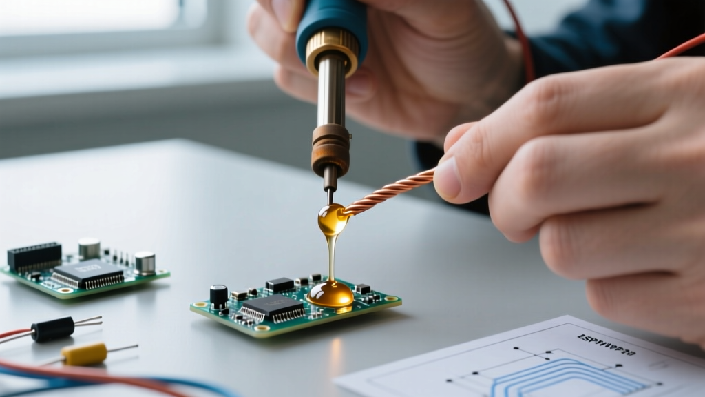
The most pervasive error among beginners is touching the solder wire directly to the iron tip, creating a molten blob, and then attempting to transfer that blob to the electrical connection. This results in a 'cold joint.' Because the base metals (the wire and the terminal) never reached the activation temperature of the flux or the melting point of the alloy, no intermetallic layer forms. The solder simply sits on top of the wire like a bead of water on a waxed car.
The Fix: Always apply the iron tip to the wire and terminal simultaneously. Wait two to three seconds for the thermal mass to absorb the heat, then feed the solder wire into the joint itself, not the iron. The joint must melt the solder.
Mistake 2: Moving the Wire Before Solidification
Solder alloys, particularly lead-free variants like SAC305 (Tin/Silver/Copper), pass through a plastic or semi-solid phase just before fully crystallizing. If the wire is jostled, bumped, or blown on with compressed air during this critical window, the crystalline structure fractures internally. This creates a 'disturbed joint,' which looks grainy, dull, and cracked under magnification, leading to intermittent electrical contact.
The Fix: Secure the wire mechanically before applying heat. Use a third-hand tool, a silicone jig, or simply bend the wire through a terminal hole to provide mechanical tension. Hold completely still until the solder loses its liquid sheen.
Mistake 3: Skipping Flux or Using the Wrong Type
Many hobbyists rely solely on the rosin core inside their solder wire. However, when soldering heavy-gauge electrical connections (e.g., 10 AWG battery cables or XT60 connectors), the internal flux burns away long before the massive thermal mass of the copper reaches soldering temperature. This leads to rapid oxidation, preventing the solder from wetting the wire.
The Fix: Apply an external, high-activity rosin-based liquid or paste flux (RMA - Rosin Mildly Activated) to the stripped wire before tinning. Never use plumbing acid flux on electrical connections, as the residual chlorides will aggressively corrode the copper strands over time, causing high-resistance failures.
Mistake 4: Overheating and Melting Wire Insulation
Leaving a high-wattage iron on a small-gauge signal wire for too long will cause the PVC or silicone insulation to melt, shrink back, and expose bare copper. This creates a severe short-circuit hazard and compromises the strain relief of the connection.
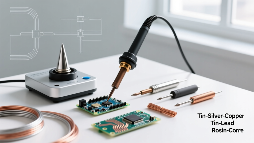
The Fix: Match your tip geometry and temperature to the wire gauge. For 24 AWG to 18 AWG wires, use a fine conical or small chisel tip at 300°C (for 60/40 Sn/Pb). For heavy 12 AWG to 8 AWG wires, switch to a massive bevel or wide chisel tip and increase the temperature to 380°C to ensure rapid heat transfer without lingering.
Mistake 5: Creating Solder Bridges on Terminal Blocks
When soldering closely spaced electrical connections, such as on screw terminal blocks or dense PCB headers, excess solder can wick across the gap, creating a short circuit. This often happens when using too much solder or an iron tip that is too large for the pad spacing.
The Fix: Use the 'drag soldering' technique with a properly tinned chisel tip, or simply use less solder. If a bridge occurs, do not try to wipe it away with a dry sponge. Apply fresh flux and use a high-purity copper desoldering braid to wick the excess solder away.
Mistake 6: Failing to Pre-Tin Stranded Wires
Attempting to solder a raw, frayed stranded wire directly to a terminal often results in stray copper strands sticking out, which can bridge to adjacent contacts. Furthermore, the solder may only wick up the outside of the bundle, leaving the inner strands unsoldered and prone to corrosion.
The Fix: Twist the stripped strands tightly, apply flux, and 'tin' the wire with a thin coat of solder before attaching it to the terminal. This binds the strands into a single solid conductor, ensuring 100% internal wetting.
Mistake 7: Ignoring Tip Oxidation
An oxidized soldering tip (black and crusty) acts as a thermal insulator. Even if the station reads 350°C, the actual temperature at the tip-to-joint interface might be below 200°C, resulting in prolonged heating times and damaged components.
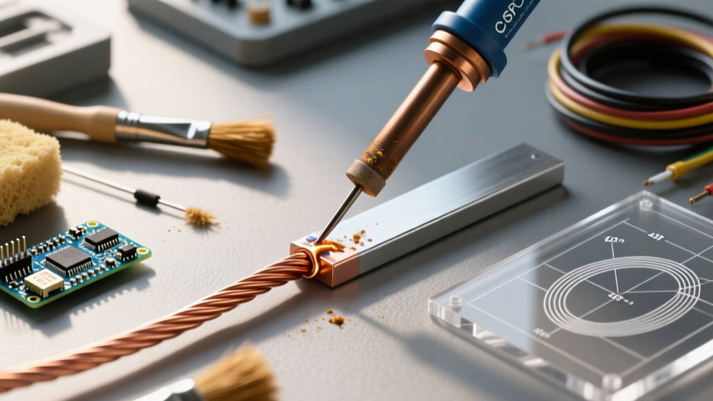
The Fix: Keep the tip tinned at all times. When not in use, leave a blob of solder on the tip to act as a sacrificial oxidation layer. Clean the tip using damp brass wool rather than a wet sponge, which causes thermal shock and micro-cracking in the iron plating.
Diagnostic Table: Identifying Bad Joints by Visual Cues
Visual inspection is the first line of defense in quality control. The IPC-A-610 standard provides strict visual criteria for electronic assemblies. Use this diagnostic matrix to troubleshoot your electrical connections.
| Visual Symptom | Probable Cause | Metallurgical Reality | Immediate Fix |
|---|---|---|---|
| Dull, grainy, or lumpy surface | Disturbed joint or incorrect alloy cooling | Fractured crystal lattice during the plastic phase | Reflow with fresh flux; hold perfectly still |
| Solder balls up and refuses to spread | Cold joint or heavy oxidation | Flux failed to remove copper oxide layer | Clean with isopropyl alcohol, apply RMA flux, reheat |
| Excessive solder obscuring wire contour | Over-application of solder | Poor wetting angle; potential hidden voids | Remove excess with 2mm copper desoldering braid |
| Charred or melted wire insulation | Excessive dwell time or wrong tip size | Thermal degradation of polymer jacket | Trim wire, re-strip, use larger tip for faster transfer |
Step-by-Step Recovery: How to Fix a Ruined Connection
When an electrical connection fails inspection, attempting to simply melt more solder over it is a recipe for disaster. The old flux is exhausted, and the copper is likely oxidized. Follow this recovery protocol to salvage the joint:
- Cool and Clean: Allow the joint to cool completely. Scrub the area with a stiff brush and 99% isopropyl alcohol (IPA) to remove any carbonized flux residue.
- Apply Fresh Flux: Generously coat the ruined joint with a high-quality rosin paste or liquid flux. This is non-negotiable; flux is the chemical engine that drives the soldering process.
- Wick the Old Solder: Place a copper desoldering braid (such as Chemtronics Type S) over the joint. Press your heated iron (set to 350°C) directly onto the braid. The capillary action will draw the old, contaminated solder out of the wire strands.
- Inspect and Re-Tin: Once the wire is clean and resembles raw copper, apply a tiny amount of fresh solder to re-tin the wire, then re-solder it to the terminal using proper heating techniques.
Pro Tip: Never use a solder sucker (desoldering pump) on stranded electrical wires. The violent mechanical shock of the pump can fracture individual copper strands inside the insulation, weakening the wire's current-carrying capacity.
Tool Calibration and Thermal Profiling
Mastering how to solder electrical connections ultimately comes down to thermal management. Every wire gauge and terminal type has a specific thermal mass. A standard 60W iron might easily solder a 22 AWG wire to a PCB pad, but it will completely stall out when applied to a heavy copper battery tab, as the tab rapidly dissipates the heat away from the joint.
For heavy-duty electrical connections, such as those found in automotive wiring, solar panel arrays, or high-discharge RC batteries, you must utilize a soldering station with active thermal feedback or a high-wattage iron (100W+). Stations like the Hakko FX-951 or Weller WE1010 utilize sensor-embedded tips that detect the exact temperature at the very front of the tip, injecting massive bursts of power the moment the tip touches a cold, heavy terminal. This ensures the joint reaches 350°C in under three seconds, melting the solder instantly without giving the heat time to travel down the wire and melt the insulation.
By respecting the metallurgy, utilizing the correct flux chemistry, and matching your thermal profile to the physical mass of your components, you will build electrical connections that rival factory-grade harnesses in both conductivity and mechanical strength. For further reading on foundational techniques, the SparkFun Soldering Guide offers excellent visual aids for beginners transitioning to advanced wire-to-board soldering.