
Evaluating the ShillehTek HX711 Pre-Soldered Large Module
When makers and engineers evaluate the ShillehTek HX711 pre-soldered large load cell amplifier module for Arduino projects, they are usually seeking a reliable bridge between raw analog strain gauges and digital microcontrollers. Building a DIY digital scale, a brewing keg monitor, or a robotic gripper force sensor requires extreme precision. The HX711 chip is a 24-bit analog-to-digital converter (ADC) designed specifically for weigh scales and industrial control applications. However, the physical breakout board you choose dictates the signal integrity long before your Arduino code even runs. This comprehensive guide dives deep into the hardware, soldering requirements, and integration nuances of the ShillehTek 'Large' variant, contrasting it with generic alternatives to help you decide if it is the right foundation for your next metrology project.
The Anatomy of the 'Large' Form Factor
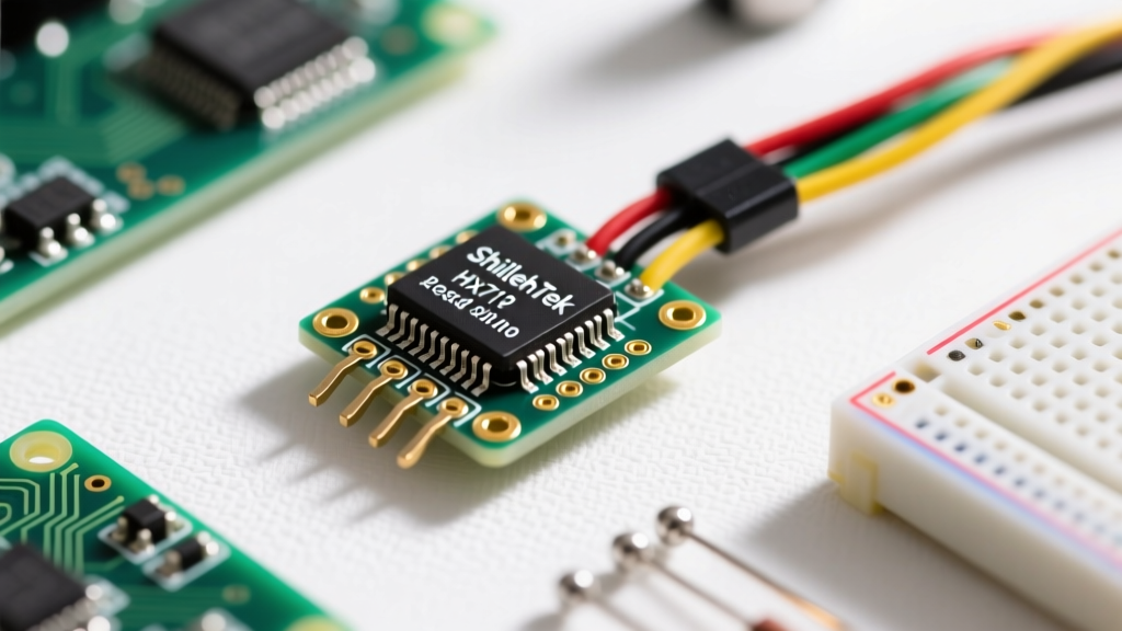
Standard HX711 breakout boards (often recognized by their small, red or blue PCBs) are incredibly cramped. The ShillehTek 'Large' version increases the PCB footprint for several critical electrical and mechanical reasons. First, it features a more robust analog ground plane. In high-gain ADC circuits, a fractured or thin ground pour can introduce ground loop noise, directly translating to jitter in your weight readings. Second, the 'Large' module typically integrates higher-capacity decoupling capacitors and a dedicated voltage regulation stage to provide a cleaner excitation voltage to the load cell.
Mechanically, the larger board accommodates heavy-duty screw terminals or pre-tinned, thick header blocks. This is a massive advantage when working with 22AWG or 20AWG shielded cables often used in industrial load cells, as standard 0.1-inch header pins on smaller boards can physically snap under the torque of thick wires.
Why 'Pre-Soldered' Matters for the Analog Front End
The term 'pre-soldered' in the context of the ShillehTek module refers to the factory assembly of the HX711 IC and its surrounding passive components. The HX711 chip itself is housed in an SSOP-16 (Shrink Small Outline Package) or sometimes a QFN package, featuring a tight 0.65mm pin pitch. Hand-soldering this IC with a standard chisel tip often results in two major failure modes:
- Flux Contamination: Rosin or water-soluble flux residues left between the high-impedance analog input pins (INA+ and INA-) can create parasitic leakage currents. This alters the baseline offset and causes the scale to drift over time as humidity changes.
- Thermal Stress: Prolonged heating of the SSOP-16 pads to clear solder bridges can degrade the internal bond wires of the IC, increasing the noise floor of the 24-bit ADC.
By utilizing automated reflow soldering at the factory, the ShillehTek module ensures pristine, uniform solder joints on the analog front end. As noted in SparkFun's HX711 Hookup Guide, keeping the analog inputs free of contamination and thermal damage is paramount for achieving the advertised 10Hz or 80Hz sample rates without erratic noise spikes.
Soldering the Load Cell: Wheatstone Bridge Best Practices
While the IC is pre-soldered, the end-user must still terminate the load cell wires to the module's E+, E-, A+, and A- pads. Load cells operate on a Wheatstone bridge circuit, outputting a differential voltage typically rated at 2mV/V. With a 5V excitation voltage, a full-scale load yields a mere 10 millivolts. At this micro-voltage level, your solder joints become part of the measurement circuit.
Wire Identification and Tinning
Load cell wire color codes are notoriously non-standard. While Red (Excitation+), Black (Excitation-), White (Signal+), and Green (Signal-) is common, you must verify this with a multimeter before applying a soldering iron. Measure the resistance between pairs: the excitation pair and the signal pair will typically show roughly equal resistance (e.g., 350 to 400 ohms), while the cross-pairs will show a slightly different resistance due to the bridge balancing resistors.
When prepping the wires for the ShillehTek screw terminals or solder pads:
- Strip exactly 6mm of insulation. Exposing too much bare wire increases the risk of shorting against adjacent terminals or the metal enclosure of your scale.
- Apply a minimal amount of high-quality rosin flux (never use acidic plumbing flux, which will corrode the copper and ruin the bridge balance).
- Tin the wires with 63/37 leaded solder or a high-reliability lead-free alloy like SAC305. Leaded solder is preferred for DIY metrology because it is less prone to micro-cracking under mechanical vibration, which can introduce intermittent resistance changes.
ShillehTek vs. Generic HX711 Breakouts: A Hardware Comparison
Understanding where the ShillehTek module sits in the market helps justify its use case. Below is a structural comparison of common HX711 boards available to Arduino developers.
| Feature | ShillehTek 'Large' Pre-Soldered | Generic Small (Red/Blue) | SparkFun / Avia Official |
|---|---|---|---|
| IC Soldering | Factory Reflow (Pristine) | Hand/Wave (Often Fluxy) | Factory Reflow (Pristine) |
| Terminals | Screw Terminals / Heavy Pins | Standard 0.1" Headers | Standard 0.1" Pads |
| Decoupling | High (10uF + 0.1uF) | Low (0.1uF only) | Moderate (Optimized) |
| Shielding | Thick Ground Plane | Thin Traces | Engineered Ground |
| Best Use Case | Industrial / Permanent Scales | Prototyping / Breadboards | Embedded PCB Design |
Filtering Noise at the Solder Joint and MCU Interface
The communication between the HX711 and the Arduino relies on a simple proprietary serial protocol using just two pins: DT (Data) and SCK (Clock). Because the ShillehTek module is often mounted inside metal enclosures or near AC motors (like in conveyor belt scales), electromagnetic interference (EMI) is a constant threat.
When soldering the DT and SCK wires to your Arduino, keep the traces as short as possible. If you must run these wires more than 10 centimeters, you should solder a small 100-ohm resistor in series with the DT line directly at the HX711 output pad. This resistor, combined with the parasitic capacitance of the wire, forms a low-pass RC filter that suppresses high-frequency RF interference before it reaches the Arduino's digital input buffer. Furthermore, ensuring a robust, star-grounded solder joint for the GND pin prevents digital switching noise from the Arduino from bleeding back into the HX711's analog ground reference.
Troubleshooting Erratic Readings: Solder vs. Software
When integrating the bogde/HX711 Arduino library, a common issue is 'drifting' or erratic tare values. Before rewriting your calibration code, inspect your soldering work.
Expert Troubleshooting Tip: If your scale readings drift upward as the ambient temperature rises, check your load cell solder joints. Using dissimilar metals (e.g., tinning a nickel-plated load cell wire with standard tin-lead solder without proper flux activation) creates a thermocouple effect. This Thermal EMF generates micro-volts of error that the 24-bit HX711 faithfully amplifies, mistaking heat for weight.
To fix this, desolder the joint, clean the wire with isopropyl alcohol and a fiberglass scratch pen to expose fresh copper, and re-solder using an active rosin-core solder. Additionally, verify that the solder mask on the ShillehTek board beneath the E+ and E- pads has not been scratched away, exposing bare copper that could oxidize and alter the excitation resistance over time.
Final Verdict on the ShillehTek Module
The ShillehTek HX711 pre-soldered large load cell amplifier module bridges the gap between fragile prototyping boards and expensive industrial transmitters. By offloading the high-precision SSOP-16 soldering to factory reflow ovens and providing robust physical terminals for heavy-gauge shielded cables, it allows the DIY engineer to focus on mechanical scale design and Arduino calibration logic. When paired with proper wire tinning, rosin flux, and star-grounding techniques, this module provides a remarkably stable foundation for high-resolution DIY metrology.