
The Physics of the Joint: Why Tip Selection Dictates Success
In professional electronics assembly and rework, the soldering iron is merely the heat source; the tip is the actual tool executing the work. When navigating the ecosystem of Weller tips soldering configurations, engineers and technicians often default to whatever tip is pre-installed on their station. This is a critical error. A mismatched tip geometry or incompatible thermal mass rating leads to prolonged dwell times, pad delamination, and compromised intermetallic copper-tin (Cu6Sn5) layer formation.
As surface mount technology (SMT) shrinks to 0201 and 01005 imperial packages in 2026, and high-density multilayer PCBs become the norm, your decision framework for selecting a Weller tip must be rooted in thermodynamics and joint geometry. This guide provides a rigorous, step-by-step methodology for selecting the exact Weller tip SKU for your specific application, ensuring compliance with IPC J-STD-001 workmanship standards.
Decoding the Weller Tip Ecosystem
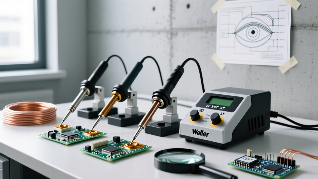
Before applying the decision framework, you must understand the hardware constraints of your Weller station. Weller utilizes proprietary active tip technology in its modern lines, where the heating element and temperature sensor are integrated directly into the tip barrel, eliminating the thermal lag found in older ceramic heater designs.
| Tip Series | Compatible Stations | Primary Use Case | 2026 Avg. Price |
|---|---|---|---|
| RT Series | WMRP, WXMP, WXMPR | Micro-SMT, 0201/01005, ultra-fine pitch | $13 - $16 |
| XNT Series | WX2020, WXR1220, WXR3 | General SMT, heavy ground planes, TH | $16 - $22 |
| LT Series | WXP80, WSP80, WE1010 | Standard TH, mid-sized SMT, wire tinning | $10 - $14 |
| ET Series | PES51, WES51 (Legacy) | Basic TH, hobbyist, general repair | $8 - $11 |
Note: Pricing reflects 2026 authorized distributor averages. Counterfeit tips often fail to meet the strict iron-plating thickness requirements, leading to rapid core erosion.
The 4-Step Weller Tips Soldering Decision Framework
Step 1: Assess the Thermal Demand (Mass & Ground Planes)
The first variable in your decision matrix is the thermal mass of the joint. A 0603 resistor on a 2-layer board requires vastly less thermal energy than a TO-220 transistor leg connected to an internal copper ground plane on a 6-layer PCB.
- Low Thermal Mass: Choose the RT Series (e.g., RT 1 conical or RT 2 chisel). The low thermal inertia prevents overheating delicate silicon dies.
- High Thermal Mass: Step up to the XNT Series (e.g., XNT C 4 or the specialized RTW 2 for heavy ground planes). According to Weller Tools, the XNT series features a high-performance heater that recovers temperature drops in milliseconds, preventing the operator from artificially raising the station temperature and risking flux burn-off.
Step 2: Match the Geometry to the Pad
A pervasive myth in electronics labs is that conical (pointed) tips are best for fine-pitch work. In reality, conical tips offer the smallest surface area contact, severely restricting heat transfer.
Expert Rule of Thumb: Always maximize the contact area between the tip and the pad without bridging adjacent pins. Chisel and bevel geometries transfer heat up to 40% faster than conical tips of the same base diameter.
Step 3: Factor in Component Pitch & Density
For QFN (Quad Flat No-leads) packages or 0.4mm pitch BGA rework, spatial clearance is your primary constraint. Here, the RTW (Rapid Thermal Work) variants or micro-knife blades (like the Weller RT MS) become mandatory. The knife blade allows you to drag-solder tight pitch IC pins while maintaining enough thermal mass to keep the solder pool fluid.
Step 4: Evaluate the Solder Alloy & Oxidation Environment
Are you using Leaded (Sn63/Pb37) or Lead-Free (SAC305/SAC405)? Lead-free alloys require operating temperatures between 340°C and 380°C. At these elevated temperatures, the iron plating on the tip oxidizes and dissolves into the solder pool at an accelerated rate. For dedicated lead-free environments, prioritize Weller's XNT series, which utilizes an advanced multi-layer coating designed to resist corrosive lead-free fluxes and high-temperature degradation.
Real-World Scenario Matrix: Which Tip for Which Job?
Use this quick-reference matrix to select your Weller tip SKU based on common 2026 bench scenarios.
| Scenario | Recommended Weller Tip SKU | Optimal Temp (SAC305) | Target Dwell Time |
|---|---|---|---|
| 0402 / 0201 SMT Passives | RT 2 (0.4mm Chisel) | 320°C - 340°C | < 1.5 seconds |
| SOIC-8 / SOP-8 ICs | LT B (1.6mm Bevel) | 330°C - 350°C | 2.0 seconds / pin |
| Multi-layer TH Capacitors | XNT C 4 (4.0mm Chisel) | 360°C - 380°C | 3.0 - 4.0 seconds |
| Heavy Copper Ground Lugs | RTW 2 (Heavy Duty Chisel) | 380°C - 400°C | 4.0 - 6.0 seconds |
| 0.5mm Pitch Drag Soldering | RT MS (Micro Knife) | 340°C | Continuous drag |
Advanced Edge Cases & Failure Modes
The "Cold Joint" Illusion
Operators frequently encounter dull, grainy solder joints and immediately assume the iron temperature is too low. They crank the station up to 400°C, destroying the tip and the PCB pad. In 90% of these cases, the issue is not temperature, but thermal transfer efficiency. The tip geometry is too small for the ground plane, acting as a bottleneck. The solution is not more heat; it is a wider chisel tip (e.g., moving from an XNT C 1.6 to an XNT C 3.2) to increase the surface area contact.
Tombstoning on Micro-Passives
When reworking 0201 components, uneven heating causes one pad's solder to reflow before the other, pulling the component upright (tombstoning). Using a specialized dual-heater setup or a highly precise RT 1 tip with a strict 1-second dwell time per pad ensures simultaneous reflow, a critical requirement noted in NASA's NEPP reliability guidelines for aerospace electronics.
Maintenance Protocols to Maximize ROI
Even the most expensive XNT tip will fail prematurely if subjected to thermal shock.
- Ditch the Damp Sponge: Wiping a 380°C tip on a wet cellulose sponge causes a rapid temperature drop of over 150°C in a fraction of a second. This micro-cracks the iron plating, exposing the copper core to rapid corrosion.
- Use Brass Wool: Always use a dry brass wire sponge. It cleans oxidation without dropping the tip temperature.
- The "Tinning" Rule: Never leave a Weller tip bare in the holder. Always apply a thick layer of rosin-core solder to the working end before placing it in the stand. This sacrificial layer oxidizes instead of the tip's iron plating.
Frequently Asked Questions (FAQ)
Can I use LT series tips on a WX2020 station?
No. The WX2020 utilizes the WXR/WX2020 handpieces which are engineered exclusively for the XNT and RT (with adapter) series. Attempting to force incompatible tip series will result in sensor errors and potential damage to the station's internal MOSFETs.
Why does my Weller RT tip turn black and stop wetting after a few hours?
This is flux carbonization and oxidation buildup. If you are using a highly active no-clean or water-soluble flux, the residue burns onto the tip at high temperatures. Reduce your idle temperature using the station's standby mode, and clean the tip with a brass sponge and specialized tip tinner (a mild abrasive compound mixed with solder powder) to restore the wetting layer.
Are third-party replacement tips worth the cost savings?
For mission-critical IPC-compliant work, absolutely not. Third-party tips often lack the internal sensor calibration and use sub-standard iron plating thicknesses. While a genuine Weller XNT tip costs around $18 and lasts for thousands of joints, a $4 clone may degrade within a week, risking expensive PCB rework and failed quality assurance inspections.