
The Role of Isolation Transformers in Mobile Power Systems
Mobile power systems in Class A motorhomes, expedition trucks, and marine vessels operate in harsh, electrically noisy environments. When connecting to external AC shore power, the risk of galvanic corrosion and lethal ground faults skyrockets. While many DIYers search online for how to wiring transformer configurations, mobile environments demand strict adherence to ABYC (American Boat & Yacht Council) and NFPA 1192 codes rather than generic residential guides.
An isolation transformer physically separates the shore power grid from your vehicle’s internal AC electrical system. It passes alternating current via magnetic induction while completely blocking direct current (DC). This breaks the galvanic path that causes underwater metals to corrode and prevents stray shore-side ground faults from energizing your vehicle's chassis.
WARNING: Working with 120V/240V AC shore power carries a severe risk of electrocution and fire. Always disconnect from shore power, shut down onboard inverters, and verify zero voltage with a CAT III multimeter before beginning any terminal work. Consult a certified marine or RV electrician if you are unsure about your specific topology.
Sizing Your Vehicle Isolation Transformer
Transformers are rated in kVA (kilovolt-amperes) rather than watts, because they must handle both real and reactive power. Undersizing your transformer will result in severe voltage sag when heavy inductive loads (like RV air conditioners or marine microwave ovens) kick on.
| Shore Service | Transformer Rating | Primary Wire (AWG) | Secondary Wire (AWG) | Breaker Size |
|---|---|---|---|---|
| 30A (120V) | 3.6 kVA | 8 AWG | 8 AWG | 30A |
| 50A (120/240V) | 7.2 kVA (or Dual 3.6) | 6 AWG | 6 AWG | 50A |
| 100A (120/240V) | 12 kVA | 2/0 AWG | 2/0 AWG | 100A |
Step-by-Step: How to Wire a Transformer for Shore Power
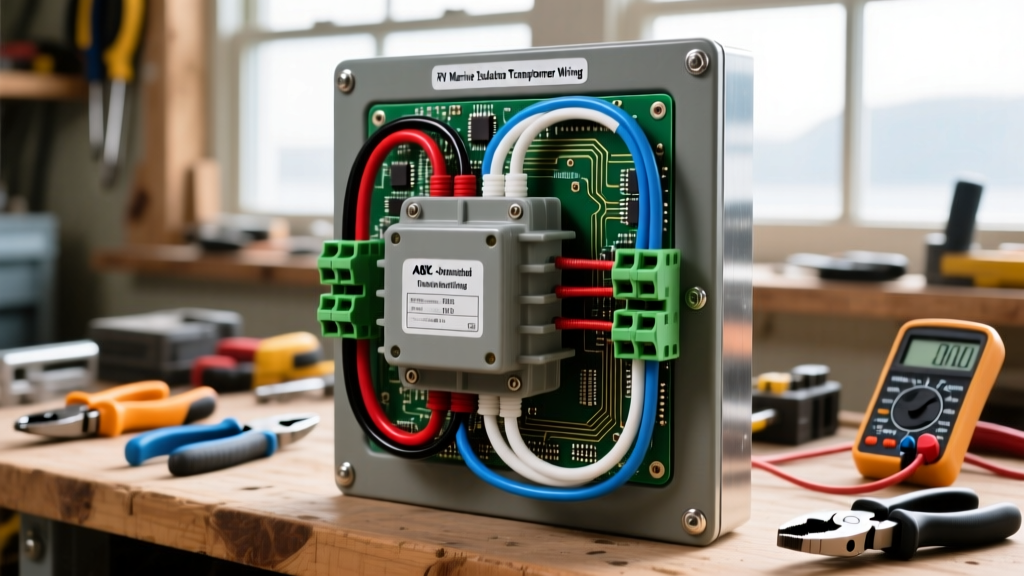
For this guide, we will reference the wiring topology of a standard marine/RV isolation transformer, such as the Victron Energy Isolation Transformer series. The wiring is divided into three distinct zones: Primary Input, Secondary Output, and the Chassis Ground Bond.
1. Primary (Shore Side) Connections
The primary side connects to your vehicle's shore power inlet. Run your marine-grade, tinned copper wire from the inlet's main breaker to the transformer's primary terminals.
- Line (L1/L2): Connect the hot shore wires to the primary input terminals.
- Neutral (N): Connect the shore neutral to the primary neutral terminal.
- Protective Earth (PE): The shore ground wire must be connected to the transformer’s metal casing grounding stud, but it must not pass through to the secondary side. This is the core mechanism of galvanic isolation.
2. Secondary (Vehicle Side) Connections
The secondary side feeds your vehicle’s internal AC distribution panel. Because the transformer creates a "locally derived source," the AC sine wave is completely regenerated.
- Line & Neutral: Route the secondary hot and neutral wires directly to your main AC distribution panel's input lugs.
- Voltage Tap Selection: Many transformers feature jumper terminals to adjust for 110V, 115V, or 120V outputs. Set this to match your region's standard (e.g., 120V for North America) to compensate for voltage drop over long shore cables.
3. The Critical Neutral-Ground (N-G) Bond
This is where 90% of DIY installations fail. According to ABYC E-11 standards, a locally derived AC source must have a Neutral-to-Ground bond. Because the isolation transformer breaks the shore-side N-G bond, you must create a new one on the secondary side.
Install a bonding wire (typically 8 AWG or 6 AWG green wire) between the secondary Neutral busbar and the vehicle’s main DC grounding busbar (the chassis or engine block). This ensures that if a hot wire shorts to your RV's metal chassis, the breaker will trip immediately rather than leaving the chassis energized.
Wire Selection and Routing in Mobile Environments
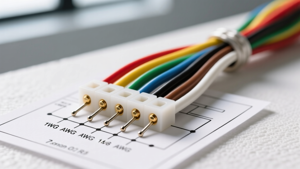
Never use solid-core THHN residential wire in a vehicle. The constant vibration of diesel engines and road travel will cause solid copper to work-harden, snap, or loosen from terminal blocks, leading to arcing and fires.
- Conductor Type: Use only stranded, tinned marine-grade wire (e.g., Ancor or Blue Sea Systems). The tin coating prevents black copper oxide corrosion in humid or salt-air environments.
- Temperature Rating: Ensure the wire insulation is rated for at least 105°C, as engine bays and enclosed generator compartments can exceed 60°C ambient.
- Terminal Crimping: Use a ratcheting hex-crimper for all ring terminals. Pull-test every connection. Apply an anti-oxidant compound like Noalox to aluminum lugs if your distribution panel uses them.
- Torque Specs: Use a calibrated torque screwdriver. For standard M6 transformer studs, the typical torque spec is 4.5 to 5.0 Nm. Over-torquing strips the threads; under-torquing creates high-resistance hot spots.
Galvanic Isolators vs. Isolation Transformers
Many vehicle owners confuse galvanic isolators with isolation transformers. A galvanic isolator is a cheaper, lighter device placed in the shore ground wire that uses diodes to block low-voltage DC galvanic currents while allowing AC fault currents to pass. However, as noted by the experts at Marine How-To, if the diodes in a galvanic isolator fail or short out, your vehicle loses its isolation and becomes vulnerable to stray current corrosion from neighboring vessels or RV park faults.
An isolation transformer is heavier and significantly more expensive, but it offers 100% fail-safe galvanic isolation and superior crew safety, as it completely eliminates the shore-side ground connection from your chassis.
Troubleshooting Mobile Transformer Failures
If your newly wired system is not functioning correctly, check these common mobile-specific failure modes:
Inrush Current Tripping Shore Breakers
Transformers draw a massive spike of current (inrush current) when first energized to magnetize the core. This can instantly trip a weak 30A RV park pedestal breaker. Solution: Install an inline soft-start module or utilize an inverter/charger with integrated PowerAssist technology to buffer the initial magnetic surge.
Overheating and Thermal Shutdown
Transformers generate heat proportional to their load. If mounted in a poorly ventilated compartment or near an exhaust manifold, the internal thermal cutoff will trip. Solution: Ensure a minimum of 4 inches of clearance on all sides for convection cooling, and install a 12V DC exhaust fan tied to a thermostat switch in the transformer compartment.
GFCI Tripping on the Secondary Side
If your RV's internal GFCI outlets trip randomly, your Neutral-Ground bond on the secondary side is likely missing, loose, or duplicated incorrectly. Solution: Verify that the N-G bond exists only at the transformer secondary output or the main panel's primary lug, and nowhere else in the sub-panel circuits.