
The Anatomy of a Precision Potentiometer Setting
When hardware engineers and DIY electronics enthusiasts refer to a potentiometer setting, they are rarely talking about the mere physical rotation of a shaft. Instead, they are defining the exact electrical node created by the wiper's position along the resistive element. Whether you are biasing a transistor, setting the cutoff frequency of an active filter, or calibrating a sensor bridge, mastering the potentiometer setting is critical for circuit stability and performance.
A potentiometer (or "pot") is fundamentally a three-terminal resistor with a sliding or rotating contact that forms an adjustable voltage divider. If only two terminals are used, it acts as a variable resistor or rheostat. According to All About Circuits, understanding the distinction between these two wiring configurations is the first step in achieving a reliable potentiometer setting. Using a pot as a voltage divider provides a stable ratio independent of the load, whereas a rheostat configuration makes the setting highly susceptible to load variations.
Taper Selection: Linear vs. Audio vs. Reverse
The "taper" of a potentiometer dictates how the resistance changes relative to the shaft's physical rotation. Selecting the wrong taper will make your potentiometer setting overly sensitive at one end of the dial and completely unresponsive at the other.
- Linear Taper (B-Taper): The resistance changes at a constant rate. This is mandatory for voltage dividers, sensor calibration, and biasing networks where a predictable mathematical relationship between shaft angle and output voltage is required.
- Audio Taper (A-Taper): The resistance changes logarithmically. Human hearing perceives volume logarithmically, so an audio taper pot ensures that a 50% rotation sounds like "half volume." Using an audio pot for a DC voltage reference will result in a highly non-linear and frustrating potentiometer setting.
- Reverse Audio Taper (C-Taper): The inverse of the audio taper, often used in specific gain control circuits or as a balance control in stereo audio mixers.
Calculating the Ideal Potentiometer Setting
To dial in a precise potentiometer setting, you must account for the resistive track's tolerance and the wiper's contact resistance. In high-precision circuits, the wiper resistance (which can range from 1Ω to 5Ω in standard carbon pots) can introduce measurable errors in low-impedance voltage dividers.
Below is a calculation matrix for a standard 10kΩ linear potentiometer connected across a 5.00V reference, demonstrating the theoretical output versus the actual output when accounting for a 2Ω wiper contact resistance and a 5% track tolerance.
| Rotation (%) | Theoretical Vout (5V) | Actual Vout (w/ 2Ω Wiper) | Setting Application |
|---|---|---|---|
| 10% | 0.500 V | 0.501 V | Low-voltage transistor bias |
| 25% | 1.250 V | 1.252 V | Op-amp offset nulling |
| 50% | 2.500 V | 2.500 V | Virtual ground generation |
| 75% | 3.750 V | 3.748 V | Comparator threshold setting |
| 90% | 4.500 V | 4.499 V | High-side limit calibration |
As shown in the table, the wiper resistance introduces asymmetry into the divider. For a deeper dive into how voltage dividers interact with varying loads, the SparkFun Voltage Divider Tutorial provides excellent foundational math.
Hardware Implementation: Trimpots vs. Panel Mounts
The physical component you choose dictates how permanent your potentiometer setting will be. We generally divide these into two categories: panel-mount pots (for user interaction) and trimpots (for factory calibration).
Selecting the Right Element Material
The resistive element material dramatically affects the longevity and stability of your setting:
- Carbon Composition: Inexpensive and common in panel-mount audio pots. However, they suffer from high wiper noise, poor temperature coefficients (often ±500 ppm/°C), and mechanical wear that causes the setting to drift over time.
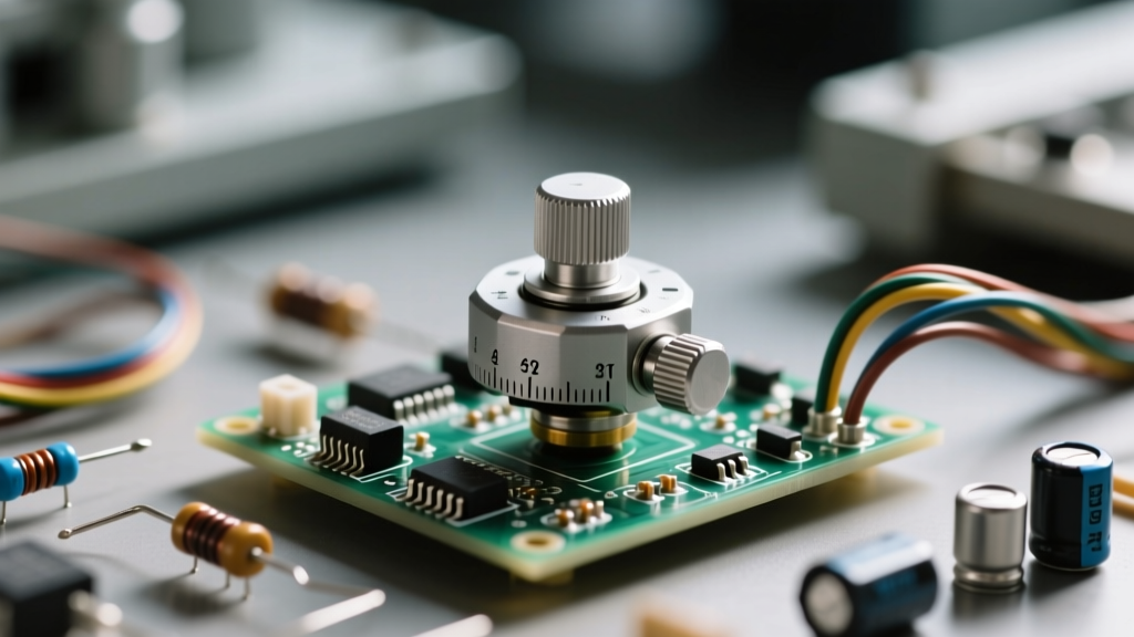
- Cermet (Ceramic-Metal): The industry standard for trimpots. Cermet offers excellent temperature stability (typically ±100 ppm/°C) and high resolution. The Bourns 3296W 25-turn trimpot is a legendary example, allowing engineers to make microscopic adjustments to lock in a precise potentiometer setting.
- Conductive Plastic: Used in high-end audio (like the Alps RK27 series) and precision joysticks. It offers incredibly smooth resolution and a long rotational life, though it is more expensive and generally limited to single-turn configurations.
The Calibration Process: Setting and Locking
Achieving the perfect potentiometer setting in a prototype or production environment requires a methodical approach. You cannot simply twist the dial with a metal screwdriver and hope for the best; the metal tool can short adjacent traces, and the magnetic field can interfere with sensitive analog nodes.
Step-by-Step Calibration
- Use Non-Inductive Tools: Always use a ceramic or high-quality plastic alignment tool. This prevents accidental shorting to the metal housing of the potentiometer.
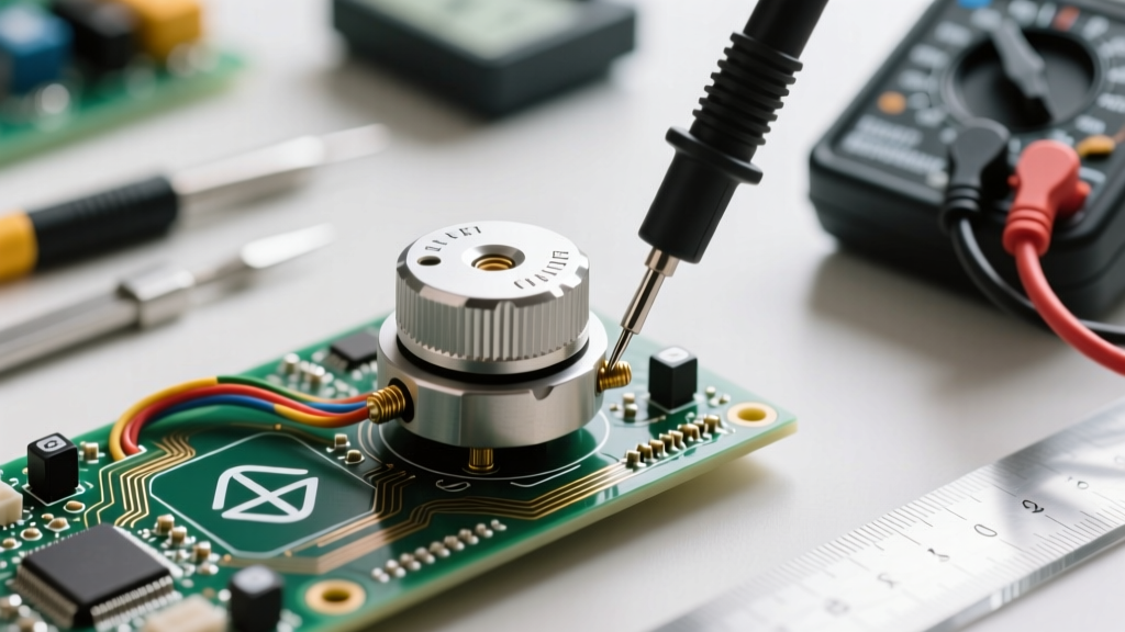
- Power the Circuit: Most potentiometer settings must be made under live operating conditions. Measure the output node with a high-impedance digital multimeter (DMM) or an oscilloscope.
- Approach from One Direction: Mechanical backlash in the wiper gear can cause the setting to shift slightly after you remove the tool. Always approach your final target voltage from the counter-clockwise direction. If you overshoot, back up significantly and approach the target again from the same direction.
- Lock the Setting: For multi-turn trimpots like the Bourns 3296, the setting can vibrate loose in high-shock environments. Apply a small drop of non-wicking, low-strength threadlocker (such as Loctite 425 or a dedicated electronics adhesive) over the adjustment screw to permanently lock the potentiometer setting in place without damaging the internal resistive track.
Pro-Tip for Multi-Turn Trimpots: When using a 25-turn trimpot, do not force the adjustment screw when you reach the physical end-stops. Forcing the screw will strip the internal brass gearing, rendering the component useless and destroying your carefully calibrated potentiometer setting.
Common Failure Modes and Troubleshooting
Even with perfect initial calibration, environmental factors can degrade a potentiometer setting over time. Understanding these failure modes is crucial for robust circuit design.
Wiper Contact Resistance and "Scratchy" Noise
In audio circuits, a degrading potentiometer setting manifests as a crackling or "scratchy" noise when the knob is turned. This is caused by oxidation or dirt on the carbon track, which momentarily breaks the electrical contact. While contact cleaners (like DeoxIT D5) can temporarily restore the connection, the physical wear on the track is permanent. In precision DC circuits, this same phenomenon causes sudden voltage spikes that can reset microcontrollers or trigger false comparator trips.
Thermal Drift
If your circuit operates in an environment with wide temperature swings, the potentiometer setting will drift. A standard carbon pot with a 1000 ppm/°C temperature coefficient will shift its resistance by 0.1% for every degree Celsius change. In a 10kΩ pot, a 50°C temperature rise changes the total resistance by 500Ω, drastically altering the voltage divider ratio. To prevent this, always specify cermet trimpots or wirewound pots (with ±50 ppm/°C) for environments exceeding 40°C.
Wiper Current Overload
A common beginner mistake is using the wiper as the primary current path for a load, such as wiring a potentiometer directly in series with an LED or a motor. The wiper contact is only rated for a few milliamps. Exceeding this rating will burn the wiper contact, permanently fusing it to the track and locking the potentiometer setting at a random, unchangeable value. Always use the potentiometer to set a reference voltage, and use a transistor or op-amp buffer to drive the actual load.
Summary Checklist for Designers
- Verify taper (Linear for DC, Audio for volume).
- Calculate wiper resistance impact on low-impedance dividers.
- Use ceramic adjustment tools for live calibration.
- Approach the final setting from a single direction to eliminate backlash.
- Apply adhesive to lock trimpots in high-vibration environments.
- Buffer the wiper output with an op-amp to prevent load-induced drift.
By treating the potentiometer setting not just as a mechanical adjustment, but as a critical electrical node subject to thermal, mechanical, and electrical stresses, you can dramatically improve the reliability and precision of your analog prototypes and production hardware.