
Silicon vs. Carbon: What Makes a Digital Potentiometer?
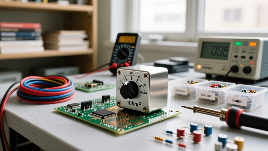
When prototyping analog circuits, audio preamps, or programmable power supplies, engineers traditionally reach for mechanical carbon or cermet track potentiometers. However, mechanical pots suffer from wiper oxidation, physical wear, and an inability to be automated. Enter the digital potentiometer (often abbreviated as digipot). Unlike a mechanical slider, a digital potentiometer is an integrated circuit (IC) that uses a string of discrete resistors and CMOS switches to simulate a variable resistance.
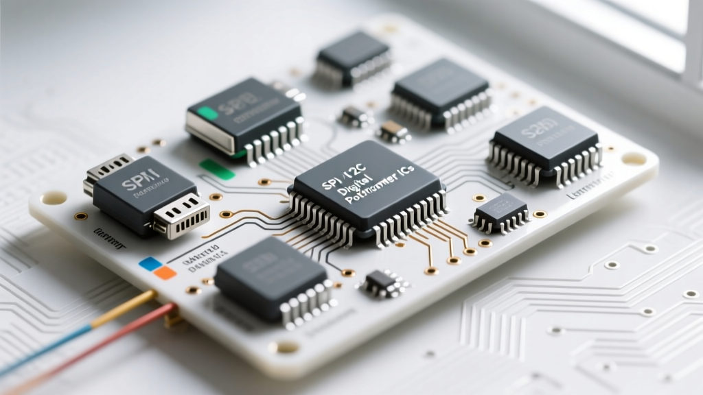
Identifying a digipot on a schematic or a populated PCB requires understanding its internal architecture. Inside the silicon die, you will typically find a resistor ladder (often an R-2R network or a series string of equal-value resistors). A digital wiper, controlled by an internal decoder, connects the output pin to one of the tap points along this ladder. Because they are built on standard CMOS processes, digipots are almost exclusively found in 8-pin, 10-pin, or 14-pin surface-mount (SOIC, TSSOP) or through-hole (DIP) packages, making them visually distinct from the bulky, 3-terminal mechanical components they replace.
Visual Identification and Pinout Decoding
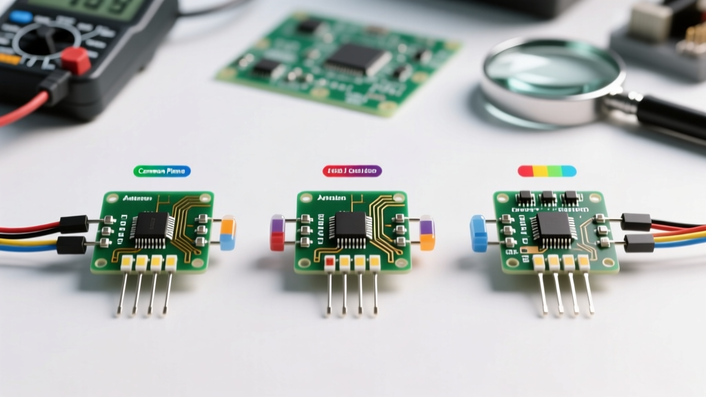
The most challenging aspect of component identification for digipots is that they look identical to standard 8-pin op-amps or 555 timers. To accurately identify a digital potentiometer, you must examine the silkscreen part number and decode the interface pins. Digipots are broadly categorized into three communication families: SPI, I2C, and Incremental (Up/Down).
The SPI Digipot (e.g., Microchip MCP41xxx)
SPI-based digipots are incredibly common in DIY microcontroller projects due to their simple shift-register logic. The Microchip MCP41010 is a staple in this category. If you are probing an unknown 8-pin IC and you find pins labeled CS (Chip Select), SCK (Clock), and SI (Serial In), you are almost certainly looking at an SPI digipot. These components act as simple input-only shift registers; you clock in an 8-bit or 10-bit command word to set the wiper position. They lack a data-out line, making them write-only devices.
The I2C Digipot (e.g., Analog Devices AD52xx)
When bus contention or pin-count conservation is a priority, engineers use I2C digipots. The Analog Devices AD5252 is a prime example of a dual-channel, non-volatile I2C digipot. Identification is straightforward: look for SDA (Serial Data) and SCL (Serial Clock) pins, alongside hardware address pins (often labeled AD0 and AD1). These address pins allow you to strap the IC to different logic levels, enabling up to four identical digipots to share the same I2C bus without address conflicts.
The Incremental Up/Down Digipot (e.g., Renesas X9Cxxx)
Not all digipots require a microcontroller. The Renesas (formerly Intersil) X9C103 family uses a simple 3-wire incremental interface. Identification relies on finding the INC (Increment), U/D (Up/Down), and CS (Chip Select) pins. By pulsing the INC pin while holding U/D high or low, the internal wiper steps up or down one position. These are frequently identified in legacy audio equipment and manual push-button calibration circuits where a full microcontroller interface is overkill.
The Hidden Trap: Wiper Resistance and Current Limits
A critical mistake made by hobbyists and junior engineers during the prototyping phase is treating a digital potentiometer exactly like a mechanical one. This leads to catastrophic failure. You must account for two silicon-specific limitations:
- Wiper Resistance ($R_w$): In a mechanical pot, the wiper resistance is negligible (fractions of an ohm). In a digipot, the CMOS transmission gate acting as the wiper introduces a series resistance, typically between 50Ω and 400Ω, depending on the specific IC and supply voltage. If you are using a 1kΩ digipot, that 100Ω wiper resistance introduces a massive 10% error into your voltage divider calculations.
- Wiper Current Limits: The internal CMOS switches are microscopic. The absolute maximum continuous DC current through the wiper pin is usually limited to 1mA to 5mA. Attempting to drive an LED directly from the wiper of a digipot will instantly vaporize the internal silicon switch, permanently locking the wiper at an erratic resistance.
Expert Troubleshooting Tip: If your digipot is outputting a fixed, unchangeable resistance, or if the wiper reads as an open circuit on your multimeter, you have likely exceeded the 5mA wiper current limit. Always buffer the wiper output with a high-impedance op-amp voltage follower (like the TL072 or MCP6001) before driving any low-impedance loads.
Volatile vs. Non-Volatile Memory States
When identifying a digipot for a replacement or new design, you must determine its memory topology. Volatile digipots (like the MCP41 series) rely on SRAM to hold the wiper position. When power is removed, the wiper resets to a default mid-scale or zero-scale position. These are ideal for audio volume ramps or temporary calibration routines.
Non-volatile digipots (like the AD5252 or Microchip MCP45x series) utilize E2CMOS (Electrically Erasable CMOS) memory. They retain their exact wiper position through power cycles, effectively acting as digital replacements for 'set-and-forget' trimpots. However, be aware that E2CMOS digipots have a finite write endurance, typically rated for 100,000 write cycles. If your firmware continuously updates the wiper position in a tight loop, you will wear out the silicon memory in a matter of hours.
Troubleshooting Common Prototyping Failures
When debugging a PCB featuring a digital potentiometer, keep these specific failure modes in mind:
- AC Signal Clipping and Latch-Up: Digipots are designed to handle DC voltages bounded by their supply rails ($V_{SS}$ and $V_{DD}$). If you pass an AC audio signal through a digipot referenced to ground, the negative half of the AC waveform will forward-bias the internal parasitic ESD protection diodes. This causes severe signal clipping and can trigger silicon latch-up, drawing massive current and destroying the IC. For AC signals, you must use AC-coupling capacitors or bias the signal to a mid-rail virtual ground.
- I2C Pull-Up Resistor Omission: If an I2C digipot is unresponsive and the SDA line reads a flat 0V, check your pull-up resistors. Digipots do not have internal I2C pull-ups. You must provide external 4.7kΩ resistors to $V_{DD}$ on both SDA and SCL lines.
- Power Sequencing Issues: Some older digipots require the logic supply ($V_{DD}$) to rise before the analog supply or terminal voltages are applied. Violating the power-up sequence can cause the internal decoder to lock into an undefined state, requiring a full power drain to reset.
Component Selection Matrix
Use the following reference table to quickly identify and select the correct digital potentiometer family for your next PCB layout:
| Part Family | Interface | Memory | Typical Price (1pc) | Best Application |
|---|---|---|---|---|
| Microchip MCP41010 | SPI | Volatile | $1.50 | MCU-controlled audio volume, temporary sensor calibration |
| Analog Devices AD5252 | I2C | Non-Volatile | $4.80 | Power supply feedback loops, set-and-forget hardware trim |
| Renesas X9C103 | Up/Down | Non-Volatile | $3.20 | Manual push-button calibration, legacy equipment repair |
| TI TPL0102 | I2C | Non-Volatile | $2.10 | High-resolution (256-step) precision voltage dividers |
By understanding the internal CMOS architecture, respecting the strict wiper current limits, and correctly identifying the communication protocol via pinout decoding, you can seamlessly integrate digital potentiometers into your designs, unlocking automated calibration and remote tuning capabilities that mechanical components simply cannot provide.