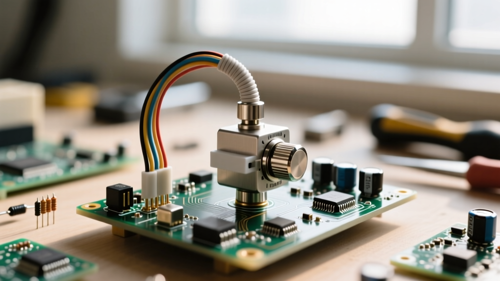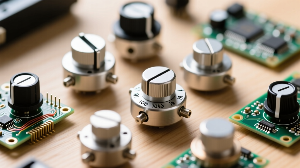

When hobbyists and engineers search for a definitive wiki potentiometer resource, they are often met with basic definitions of three-terminal variable resistors. However, true proficiency in circuit design requires moving beyond elementary concepts and diving deep into manufacturer datasheets. Whether you are designing a high-fidelity audio mixer, a precision voltage reference, or a rugged industrial joystick, the datasheet holds the critical metrics that dictate your component's real-world performance. In this comprehensive guide, we break down the exact specifications, hidden failure modes, and material science behind modern potentiometers.
The Anatomy of a Potentiometer Datasheet
A typical datasheet for a variable resistor is divided into electrical, mechanical, and environmental specifications. While the resistance value (e.g., 10kΩ) and power rating (e.g., 0.5W) are the first numbers designers look at, they barely scratch the surface. To truly understand how a potentiometer will behave in your circuit, you must decode the part number and analyze the resistive element material.
Decoding the Part Number: Bourns 3296W vs. 3386P
Let us examine the industry-standard Bourns 3296 Trimpot Datasheet. A part number like 3296W-1-103LF contains vital mechanical data:
- 3296: The series designation, indicating a 3/8-inch square, multiturn cermet trimpot.
- W: The termination and adjustment style. 'W' denotes top-adjust with wire leads. Other variants include 'P' (top-adjust, PC pins) and 'X' (side-adjust).
- 1: The pinout configuration (standard 1-2-3).
- 103: The resistance code. 10 x 10^3 = 10,000 ohms (10kΩ).
- LF: Lead-free (RoHS compliant).
Understanding these suffixes prevents catastrophic prototyping errors, such as ordering a side-adjust trimpot for a PCB layout designed for top-adjust clearance.
Electrical Specifications: Beyond the Resistance Value
The most misunderstood section of any potentiometer wiki or datasheet is the electrical characteristics table. Two metrics in particular—Contact Resistance Variation (CRV) and Equivalent Noise Resistance (ENR)—will make or break precision analog circuits.
Contact Resistance Variation (CRV) and Wiper Noise
CRV measures the maximum change in resistance between the wiper and the resistive track as the shaft is rotated. It is typically specified in milliohms or as a percentage of the total resistance. For a 10kΩ carbon composition pot, a CRV of 1% means the wiper resistance can fluctuate by up to 100Ω during rotation. In a high-impedance audio circuit, this fluctuation manifests as 'zipper noise' or crackling. For precision applications, engineers must specify conductive plastic elements, which offer CRV values as low as 0.1%, ensuring buttery-smooth voltage transitions.
The Great Taper Confusion: Audio vs. Linear
One of the most dangerous pitfalls in component sourcing is the lack of global standardization for taper codes (the curve defining how resistance changes relative to shaft rotation). If you are sourcing parts globally, you must consult the specific manufacturer's taper chart.
| Taper Type | Asian/Alpha Code | US/EU (Bourns/BTE) Code | Resistance at 50% Rotation | Primary Application |
|---|---|---|---|---|
| Linear | B | A or B | ~50% (5kΩ on a 10k pot) | Voltage dividers, position sensing |
| Audio (Logarithmic) | A | C or F | ~10% to 15% (1kΩ - 1.5kΩ) | Audio volume controls |
| Reverse Audio | C | D or I | ~85% to 90% | Panning pots, balance controls |
Expert Prototyping Insight: Human hearing perceives loudness logarithmically. If you use a Linear (B) taper for a volume knob, the audio will sound like it jumps from silent to deafening in the first 20% of the knob's travel. Always verify the taper curve graph in the datasheet rather than relying solely on the printed letter code.
Mechanical & Environmental Limits
Datasheets provide strict mechanical boundaries that dictate the physical lifespan of the component. When designing for longevity, pay close attention to the Rotational Life and Operating Torque specifications.
Cycle Life and Element Materials
The rotational life cycle is heavily dependent on the resistive element material:
- Carbon Composition: Cheap and common, but limited to 10,000 - 15,000 cycles. Prone to wiper wear and track degradation.
- Cermet (Ceramic + Metal): Used in trimpots like the Bourns 3296. Designed for calibration, not continuous adjustment. Usually rated for only 200 to 1,000 cycles. Exceeding this will physically grind away the cermet track.
- Conductive Plastic: The gold standard for continuous-use faders and joysticks. Rated for 1,000,000+ cycles with incredibly low wiper noise. CUI Devices notes that conductive plastic elements also offer superior temperature stability compared to carbon.
Rotational Torque Specs
Torque is measured in gf·cm (gram-force centimeters). A standard panel-mount audio pot might have a torque of 2-20 gf·cm. If you are designing a motorized fader system (like those found in automated mixing consoles), you must match the potentiometer's maximum starting torque with your DC motor's stall torque to prevent gear stripping.
Real-World Failure Modes & Mitigation Strategies
Even the highest-quality potentiometers will eventually fail if subjected to hostile environments or improper circuit design. Understanding these failure modes is what separates a novice from a senior hardware engineer.
Oxidation and the 'Dead Spot'
The most common failure in aging carbon pots is the formation of a non-conductive oxide layer on the resistive track or the wiper contact. This results in 'dead spots' where the wiper loses electrical continuity, causing the output voltage to float or snap to the rails. Mitigation: Never route DC current directly through the wiper in high-reliability circuits. Instead, use the potentiometer as a voltage divider feeding a high-impedance buffer op-amp (like the OPA1612). The op-amp draws virtually zero current, preventing micro-arcing and wiper oxidation.
Environmental Ingress (IP Ratings)
Standard open-frame potentiometers offer zero protection against dust, moisture, or flux residue. If your PCB will be exposed to harsh environments, you must specify sealed potentiometers. Look for datasheets that explicitly state compliance with IP67 or mention 'O-ring shaft seals' and 'epoxy-sealed terminals'. Washing a PCB with unsealed pots will trap isopropyl alcohol and flux inside the housing, creating a conductive sludge that permanently ruins the track resistance.
Summary: Designing with Intent
Treating a potentiometer as a simple 'variable resistor' is a recipe for noisy, unreliable prototypes. By utilizing this wiki potentiometer framework and rigorously analyzing datasheet metrics like CRV, taper curves, and element materials, you can select the exact component required for your application. Whether you need the rugged, high-cycle reliability of a conductive plastic fader for a studio mixer, or the precise, stable calibration of a cermet trimpot for a medical sensor, the answers are always hidden in the fine print of the datasheet.