
Decoding the Potentiometer Pinout: Beyond the Three Pins
When prototyping analog circuits, the potentiometer is often treated as a simple, foolproof component. You solder three wires, turn a knob, and expect a smooth voltage sweep. However, misinterpreting a potentiometer pinout is one of the most common causes of reversed controls, scratchy audio, and unstable voltage dividers in DIY electronics. To truly master variable resistors, you must look past the physical casing and dive directly into the manufacturer datasheets.
In this datasheet breakdown, we will dissect the standard 3-terminal mechanical potentiometer, analyze how manufacturers like Bourns and ALPS document their pin configurations, and explore the critical differences between linear and logarithmic tapers. Whether you are wiring a Bourns 3296W cermet trimpot for a precision power supply or an ALPS RK09 carbon-track pot for an audio mixer, understanding the exact pinout nomenclature is non-negotiable for reliable circuit design.
Anatomy of a Datasheet: Identifying the Wiper, CW, and CCW Terminals
Open any standard datasheet for a panel-mount or trimmer potentiometer, and you will be greeted by mechanical outline drawings and schematic symbols. The universal standard for a 3-pin potentiometer assigns specific roles to each terminal based on rotational direction. Let us break down the standard pinout using the industry-standard Bourns 3296 Multi-Turn Trimpot Datasheet as our reference point.
On page 2 of the Bourns documentation, the pinout is explicitly mapped to the physical orientation of the component when viewed from the top (with the adjustment screw facing up and the pins pointing down). The terminals are designated as follows:
| Pin Number | Datasheet Designation | Electrical Function | Mechanical Correlation |
|---|---|---|---|
| Pin 1 | CCW Terminal | Fixed End A (Ground/Reference) | Counter-Clockwise End Stop (0% Rotation) |
| Pin 2 | Wiper Terminal | Variable Output (The Sweep) | Moves along the resistive track |
| Pin 3 | CW Terminal | Fixed End B (VCC/Signal In) | Clockwise End Stop (100% Rotation) |
The Schematic Symbol Translation
Datasheets typically represent the potentiometer as a standard resistor symbol with an arrow pointing at the center. This arrow is Pin 2 (the wiper). A critical mistake made by beginners is assuming Pin 1 and Pin 3 are interchangeable. While swapping them will not destroy the component, it will invert the behavior of your circuit. If you wire Pin 1 to VCC and Pin 3 to Ground, turning the knob clockwise will decrease the output voltage instead of increasing it—a frustrating bug in volume controls and motor speed drivers.
Linear (B-Taper) vs. Audio (A-Taper): How Datasheets Dictate Wiring
The physical pinout (1, 2, 3) only tells half the story. The internal geometry of the resistive track dictates how the resistance changes relative to the wiper's physical position. This is known as the 'taper', and it is heavily detailed in the electrical specifications section of the datasheet.
If you examine the Bourns PTV09A Audio Potentiometer Datasheet, you will find a section titled 'Taper'. Manufacturers use specific alphanumeric codes to define this behavior, which directly impacts how you must wire Pin 1 and Pin 3 in audio applications.
- B-Taper (Linear): The resistance changes at a constant rate. At 50% physical rotation, the resistance between Pin 1 and Pin 2 is exactly 50% of the total resistance. This is required for voltage dividers, sensor calibration, and LED dimming.
- A-Taper (Audio/Logarithmic): Human hearing perceives loudness logarithmically, not linearly. An A-taper potentiometer is engineered so that at 50% rotation, the resistance ratio is typically around 10% to 15% of the total track. This provides a smooth, natural-sounding volume swell.
- C-Taper (Reverse Audio): The inverse of the A-taper, sometimes used in specific synthesizer filter sweeps or vintage equipment restoration.
Reading the Taper Charts
Datasheets include a graph with the X-axis representing 'Rotation Angle (%)' and the Y-axis representing 'Resistance Ratio (%)'. When wiring an A-taper pot for a stereo amplifier, you must ensure that Pin 1 is tied to Ground and Pin 3 is tied to the Audio Signal Input. If you reverse Pin 1 and Pin 3 on a logarithmic pot, the volume will remain almost silent for 70% of the knob's travel, and then aggressively spike to maximum volume in the final 30% of the rotation.
Rheostat Mode: Tying Off Pin 1 or Pin 3
Frequently, engineers need a variable resistor (rheostat) rather than a voltage divider. This requires a 2-pin configuration. The instinctive approach is to simply leave Pin 1 or Pin 3 unconnected (floating) and use Pin 2 and the remaining fixed terminal. This is a severe design flaw.
If the wiper (Pin 2) experiences micro-vibrations, thermal expansion, or mechanical wear, it can momentarily lift off the carbon or cermet track. If Pin 3 is left floating, this momentary disconnect results in an open circuit (infinite resistance). In a power supply feedback loop or an audio gain stage, an open circuit can cause voltage spikes, oscillation, or loud, damaging 'pops' through a speaker.
The Datasheet-Approved Solution: Always short the wiper (Pin 2) to the unused fixed terminal (Pin 3). If the wiper lifts, the circuit seamlessly defaults to the maximum fixed resistance of the track, maintaining a closed loop and preventing catastrophic open-circuit failures.
Real-World Failure Modes: When the Wiper Bounces
Datasheets do not just list ideal specifications; they define the limits of degradation. When analyzing a potentiometer pinout for high-reliability applications, you must look for the Contact Resistance Variation (CRV) specification.
CRV measures the maximum change in resistance between the wiper (Pin 2) and the fixed terminals (Pin 1 and 3) as the shaft is rotated. For a cheap carbon-track potentiometer, the CRV might be specified as 3% of the total resistance or 3 ohms, whichever is greater. In precision analog-to-digital converter (ADC) reference circuits, a 3-ohm wiper bounce can introduce massive amounts of noise into your digital readings.
For high-precision prototyping, engineers specify cermet (ceramic-metal) or conductive plastic track potentiometers. Cermet trimpots, like the Bourns 3296 series, offer vastly superior CRV ratings and can withstand hundreds of adjustment cycles without degrading the resistive element, ensuring the wiper maintains a clean, low-noise electrical connection to the track.
Digital vs. Mechanical: The SPI/I2C Pinout Shift
As we transition from purely analog prototyping to mixed-signal microcontroller designs, the mechanical potentiometer is often replaced by a digital potentiometer (digipot). The pinout paradigm shifts entirely from analog terminals to digital communication buses.
Take the Microchip MCP4131 Digital Potentiometer as an example. Instead of three analog pins, the MCP4131 features an 8-pin SOIC/PDIP package. The datasheet defines the following pinout:
- Pins 5, 6, 7 (P0B, P0W, P0A): These act exactly like Pins 1, 2, and 3 on a mechanical pot, but the 'wiper' is moved via digital registers.
- Pin 1 (CS): Chip Select (Active Low).
- Pin 2 (SCK): Serial Clock.
- Pin 3 (SDI): Serial Data In.
When integrating a digipot, you must remember that the P0A and P0B terminals are strictly limited to the voltage rails of the VDD and VSS pins. Unlike a passive mechanical potentiometer which can happily divide a 24V analog signal, feeding 24V into the P0A pin of an MCP4131 will instantly destroy the internal CMOS switching matrix.
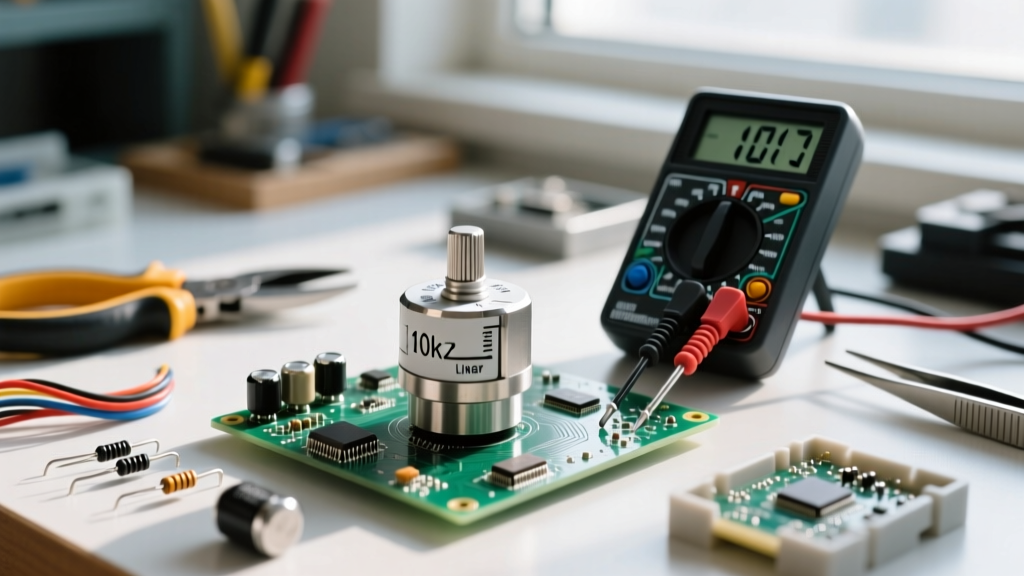
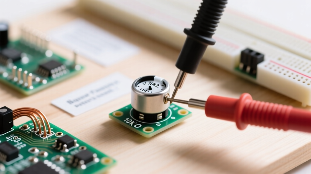
Pro-Tip from the Bench: Always measure the resistance between Pin 1 and Pin 3 with a multimeter before soldering a mechanical pot to a PCB. This verifies the total track resistance and confirms you have identified the fixed ends correctly, isolating Pin 2 as the true wiper before applying power to your prototype.
By treating the potentiometer not just as a physical knob, but as a precisely documented component governed by its datasheet, you eliminate reversed controls, prevent open-circuit noise, and ensure your analog and mixed-signal prototypes perform flawlessly on the first power-up.