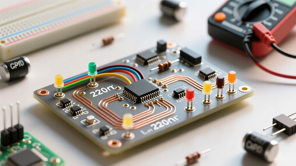

When you unbox a standard beginner electronics kit—whether it is an Elegoo Super Starter Kit, a Rexqualis bundle, or a Freenove tutorial pack—you will inevitably find a small, four-legged component nestled in the anti-static bag. This is the 5mm through-hole RGB LED. While a standard LED only requires two pins and a single current-limiting resistor, the RGB LED is essentially three separate light-emitting diodes packed into a single epoxy housing. Mastering this component is a rite of passage for hobbyists, bridging the gap between basic digital output and the nuanced world of analog color mixing.
Anatomy of a Starter Kit RGB LED
Unlike a standard two-pin LED, an RGB LED features four leads. Three of these leads correspond to the individual anodes (positive terminals) for the Red, Green, and Blue semiconductor dies inside the package. The fourth lead is the 'common' pin, which is physically connected to all three dies internally.
Starter kits typically include one of two variants:
- Common Cathode (CC): The common pin is connected to the ground (GND). You apply a positive voltage to the individual color pins to illuminate them. This is the most common type found in Arduino starter kits.
- Common Anode (CA): The common pin is connected to the positive supply voltage (VCC). You connect the individual color pins to ground (or sink current via a microcontroller) to illuminate them.
Identifying the pins: If you look at the RGB LED from the bottom, the longest leg is almost always the common pin (Pin 2). Pin 1 is Red, Pin 3 is Green, and Pin 4 is Blue. Additionally, the epoxy lens will usually have a flattened edge on the side of the Red pin to help you orient the component when the leads are trimmed.
The Forward Voltage Trap: Why Your Blue Die Burns Out
The most critical concept to understand about an RGB LED is that it is not a single, uniform component. It is a hybrid of three distinct semiconductor materials, each with its own unique electrical requirements. According to SparkFun's comprehensive LED tutorial, the color of an LED is determined by the bandgap energy of the materials used to create the PN junction.
- Red Die: Typically made from Aluminum Gallium Indium Phosphide (AlGaInP). It has a low forward voltage ($V_f$) of roughly 1.8V to 2.2V.
- Green and Blue Dies: Typically made from Indium Gallium Nitride (InGaN). They require a much higher forward voltage, usually between 3.0V and 3.4V.
The Beginner Mistake: Many beginners attempt to save time by placing a single current-limiting resistor on the common cathode pin, assuming it will protect all three colors equally. This is a catastrophic error. If you apply 5V and use a single resistor, the Red die (with its lower 2.0V threshold) will effectively 'clamp' the voltage at the common node. The Blue and Green dies will receive insufficient voltage to overcome their 3.2V thresholds and will remain completely dark. Meanwhile, the Red die will attempt to draw all the available current, rapidly overheating and snapping its microscopic internal gold bond wire. You must always use three separate resistors—one for each color channel.
Calculating Current Limiting Resistors
To safely operate an RGB LED from a standard 5V Arduino Uno or a 3.3V ESP32 microcontroller, we use Ohm's Law: $R = (V_{source} - V_f) / I$. Assuming a target forward current ($I$) of 20mA (0.02A) per channel, here is the exact resistor data you need for your prototyping breadboard.
| Color Channel | Typical $V_f$ | Target Current | Resistor @ 5V (Calculated) | Standard E12 Resistor to Use |
|---|---|---|---|---|
| Red | 2.0V | 20mA | 150 Ω | 150 Ω or 220 Ω |
| Green | 3.2V | 20mA | 90 Ω | 100 Ω or 150 Ω |
| Blue | 3.2V | 20mA | 90 Ω | 100 Ω or 150 Ω |
Note: If you are using a 3.3V microcontroller like the Raspberry Pi Pico or ESP32, the voltage headroom for the Blue and Green channels is extremely tight (3.3V - 3.2V = 0.1V). You will need a very low resistance (e.g., 5 Ω) or you must accept that the blue and green channels will be significantly dimmer than the red channel on 3.3V logic.
Pulse Width Modulation (PWM) for True Color Mixing
If you simply use digitalWrite(HIGH) on the Red and Blue pins, you will get a harsh, binary magenta. To create smooth pastel colors, warm whites, or deep oranges, you must utilize Pulse Width Modulation (PWM). As detailed in the Arduino analogWrite() documentation, PWM rapidly switches the power on and off at a frequency of roughly 490Hz. The human eye's persistence of vision integrates these rapid flashes into a perceived analog brightness level.
By assigning a value between 0 (fully off) and 255 (fully on) to each channel, you can mix over 16.7 million theoretical colors. Here is a practical 'recipe' chart for common colors using an 8-bit PWM scale (Common Cathode configuration):
- Warm White: Red 255, Green 150, Blue 50
- Cyan: Red 0, Green 255, Blue 255
- Amber / Orange: Red 255, Green 100, Blue 0
- Deep Purple: Red 128, Green 0, Blue 128
- Pink: Red 255, Green 50, Blue 100
Diffused vs. Water-Clear Lenses: An Optical Choice
When sourcing replacement RGB LEDs for your kit, you will encounter two lens types. Starter kits almost exclusively include diffused RGB LEDs, which feature a milky, opaque epoxy coating. This diffusion acts as an optical integrator, scattering the light from the three separate dies so they blend into a single, unified color before exiting the lens.
Conversely, water-clear RGB LEDs have perfectly transparent epoxy. While they are significantly brighter and project light further, they fail to mix colors effectively. If you look at a wall illuminated by a water-clear RGB LED, you will see three distinct dots of red, green, and blue light rather than a single blended color. For breadboard prototyping and status indicators, always choose the diffused variant.
Pro-Tip for Continuous White Light: If you plan to leave your RGB LED on 'White' (all three channels at 255) for extended periods, be aware that the common pin must sink or source the combined current of all three dies (20mA + 20mA + 20mA = 60mA). While most 5mm LEDs can handle this peak current, it generates significant internal heat. For continuous duty cycles, reduce your PWM values to 128 (roughly 10mA per channel) to ensure the internal bond wires do not degrade over time.
Troubleshooting Common RGB LED Wiring Mistakes
Even with the correct schematic, beginners frequently encounter issues when prototyping. Use this diagnostic checklist if your RGB LED is behaving erratically:
- Colors are inverted or wrong: You have likely misidentified the common pin. If you are treating a Common Anode LED as a Common Cathode, the colors will behave inversely (a PWM value of 0 will turn the channel fully ON, and 255 will turn it OFF). Swap your common pin connection from GND to 5V (or vice versa) and invert your code logic.
- Only one color fades, others snap on/off: You have wired the non-fading colors to standard digital pins instead of PWM-capable pins. On an Arduino Uno, PWM pins are specifically marked with a tilde (~) symbol, typically pins 3, 5, 6, 9, 10, and 11.
- The LED flickers randomly: Breadboard contact bounce or a floating common pin can cause this. Ensure your ground wire is securely seated in the power rail, and verify that your microcontroller's GND is properly tied to the breadboard's common ground bus.
- The Red channel is incredibly dim: You may have accidentally swapped the 220 Ω resistor onto the Red channel and the 100 Ω resistors onto the Blue/Green channels. While 220 Ω is safe, it will restrict the Red die's current much more severely than the higher-voltage dies, throwing off your white-balance calibration.
Understanding the physical and electrical nuances of the RGB LED transforms it from a frustrating four-legged puzzle into a powerful tool for user interface design. By respecting the distinct forward voltages of the internal semiconductor dies and leveraging PWM for analog color blending, you can elevate your starter kit projects from simple blinking lights to sophisticated, multi-state visual indicators.