
Anatomy of a Potentiometer: Beyond the Knob
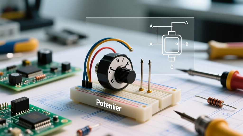
A potentiometer (often abbreviated as a "pot") is a three-terminal variable resistor that acts as an adjustable voltage divider. While beginners often view them simply as volume knobs or dimmer switches, accurate potentiometer identification requires understanding the internal electromechanical architecture. At its core, a pot consists of a resistive track, a sliding contact known as a wiper, and three electrical terminals. Terminal 1 is the counter-clockwise (CCW) end, Terminal 2 is the wiper, and Terminal 3 is the clockwise (CW) end.
When identifying an unknown component on a salvaged PCB or selecting a replacement for a vintage amplifier, the physical size and shaft type are only the beginning. The true differentiator lies in the resistive track material, which dictates the component's lifespan, noise floor, and power handling capabilities.
Resistive Track Materials Decoded
- Carbon Composition: The most common and inexpensive type (typically $0.10 to $0.50). They offer good resolution but are prone to mechanical wear, generating "scratchy" noise over time as carbon dust accumulates.
- Cermet (Ceramic-Metal):strong> Used primarily in trimpots and precision calibration circuits. Cermet tracks handle higher temperatures and offer excellent stability, but they have a shorter rotational lifespan (around 200 cycles) compared to panel-mount pots.
- Conductive Plastic: The gold standard for high-end audio equipment and motorized studio faders (like the renowned Alps RK27 series, priced upwards of $15-$25). They offer virtually infinite rotational lifespans and ultra-low wiper noise.
- Wirewound: Constructed from nichrome or similar resistance wire wound around a core. Used for high-power applications (2W to 10W+), but they suffer from step-wise resolution rather than a smooth, continuous sweep.
Decoding the Markings: Resistance, Tolerance, and Tapers
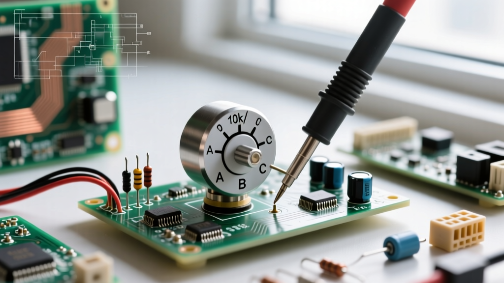
Most potentiometers feature stamped alphanumeric codes on their metal casing or bakelite base. Identifying the resistance value is usually straightforward: a marking of "10K" or "103" indicates 10,000 ohms. A marking of "502" indicates 5,000 ohms (50 x 10^2). However, the taper—the mathematical relationship between shaft rotation and resistance change—is where most DIYers make critical errors.
The "A" vs "B" Taper Dilemma
The taper code is usually denoted by a letter preceding or succeeding the resistance value (e.g., B10K or 10KA). Here is the definitive breakdown for standard global identification:
- Linear Taper (B): The resistance changes at a constant rate relative to shaft rotation. At 50% rotation, the resistance between the wiper and one end is exactly 50% of the total value. Used for panning circuits, motor speed controls, and oscilloscope calibrations.
- Audio/Logarithmic Taper (A): Human hearing perceives volume logarithmically, not linearly. An audio taper pot mimics this, providing fine control at low volumes and rapid changes at high volumes. At 50% rotation, the resistance is typically around 10% to 15% of the total value.
- Reverse Logarithmic (C): The inverse of the audio taper, occasionally used in specialized tone stack circuits or vintage synth filter sweeps.
Pro-Tip: The Asian vs. US Marking Trap. If you are salvaging parts from Japanese or Chinese electronics, "B" almost universally means Linear, and "A" means Audio. However, in some older American-manufactured gear, these designations were occasionally swapped. Always verify an unmarked or suspicious potentiometer with a multimeter by measuring the wiper-to-ground resistance at the exact 12 o'clock (50%) shaft position.
Physical Form Factors and Mounting Styles
When replacing a broken potentiometer, matching the electrical specifications is useless if the physical form factor does not fit your enclosure or PCB footprint. According to Bourns Trimmer Potentiometers documentation, identifying the mechanical series is vital for PCB layout.
- Panel Mount (Solder Lug vs. PCB Pin): Standard 16mm (Alpha RD9012) or 24mm pots feature a threaded bushing for mounting to a chassis. They come with either PCB pins for automated wave soldering or elongated solder lugs for point-to-point hand wiring.
- Multi-Turn Trimpots (e.g., Bourns 3296W): These blue, rectangular components feature a top-mounted adjustment screw requiring 25+ full rotations to traverse the track. They are used for precision biasing in amplifiers and voltage reference trimming.
- Single-Turn Trimpots (e.g., Bourns 3386): Circular, cermet-based pots used for general-purpose, non-critical circuit calibration where cost is a priority over precision.
- Slide Potentiometers: Linear travel pots used in graphic equalizers and lighting desks. Identification requires measuring the physical travel length (e.g., 60mm, 100mm) and checking for dual-gang configurations (stereo).
Common Failure Modes and Multimeter Diagnostics
Potentiometers are mechanical components, making them the most frequent point of failure in analog electronics. Before desoldering a suspected bad pot, perform this definitive three-step multimeter diagnostic:
- Total Resistance Check: Set your DMM to the appropriate ohms range. Place probes on Terminal 1 (CCW) and Terminal 3 (CW). Turn the shaft. The reading should remain perfectly static (e.g., 10.1kΩ for a 10k pot with a 5% tolerance). If the reading fluctuates wildly, the internal track is cracked or severely degraded.
- Wiper Continuity & Linearity: Move one probe to Terminal 2 (Wiper). Slowly rotate the shaft from CCW to CW. The resistance should sweep smoothly from near 0Ω up to the total resistance value. Any sudden jumps, dropouts, or "dead zones" indicate carbon track wear or a lifted wiper contact.
- The "Scratchy" Audio Test: If the pot measures fine on a DC multimeter but causes static in an audio amplifier, the wiper is suffering from micro-oxidation or carbon dust buildup. A targeted application of DeoxIT D5 contact cleaner often resolves this. If the noise persists after cleaning, the track is physically gouged and the component must be replaced.
For a deeper dive into how these variable resistors manipulate current and voltage in a circuit, review the foundational guides on All About Circuits.
Wiring Configurations: Rheostat vs. Voltage Divider
How you wire the three pins fundamentally changes the component's function. Understanding this distinction is crucial for circuit troubleshooting and reverse-engineering PCBs.
1. The Voltage Divider (All 3 Pins Used): Input voltage is applied to Terminal 3, and Terminal 1 is tied to ground. The wiper (Terminal 2) outputs a variable voltage between 0V and Vin. This is how volume controls and sensor calibration circuits operate. For a comprehensive breakdown of the math behind this setup, consult the SparkFun Voltage Dividers tutorial.
2. The Variable Resistor / Rheostat (2 Pins Used): Only the wiper and one end terminal are wired into the circuit, usually to control current flow (e.g., LED dimming or motor speed).
The Wiper Tie Trick: When wiring a pot as a 2-pin rheostat, always solder a jumper wire between the wiper (Pin 2) and the unused end terminal (Pin 3). If the wiper momentarily loses contact with the track due to vibration or wear, the circuit defaults to the maximum resistance of the track rather than snapping to an open circuit (infinite resistance), which could destroy downstream transistors or cause a motor to stall violently.
Selecting the Right Potentiometer for Your Build
Use the following decision matrix to ensure you select the correct component for your next prototyping or repair project.
| Application Scenario | Recommended Type & Material | Ideal Taper | Example Part Number | Est. Price (USD) |
|---|---|---|---|---|
| Guitar Pedal / Audio Volume | Panel Mount, Carbon/Conductive Plastic | Audio (Log) | Alpha RD9012F / Alps RK27 | $0.80 - $18.00 |
| Op-Amp Bias Trimming | Multi-Turn Trimpot, Cermet | Linear | Bourns 3296W-1-103LF | $1.50 - $2.50 |
| High-Power Dummy Load | Panel Mount, Wirewound | Linear | Vishan 50W Wirewound | $12.00 - $25.00 |
| Microcontroller Sensor Cal. | Single-Turn Trimpot, Cermet | Linear | Bourns 3386P-1-502LF | $0.40 - $0.90 |
Power Ratings and Thermal Derating
A frequently overlooked aspect of potentiometer identification is the power rating. Most standard 16mm carbon panel pots are rated for just 0.125W (1/8th watt). If you attempt to use a standard carbon pot to dim a 12V, 1A halogen bulb, the 12W dissipation will instantly vaporize the carbon track and potentially start a fire. For power control applications, you must identify heavy-duty wirewound pots rated for 2W to 10W, or better yet, use a low-power potentiometer to feed a control voltage into a MOSFET or power transistor, keeping the high current entirely out of the mechanical wiper.
Furthermore, all potentiometers are subject to thermal derating. A pot rated for 0.5W at 70°C will typically derate linearly to 0W at 125°C. When designing high-density PCBs or repairing enclosed amplifiers, ensure the potentiometer is not mounted directly adjacent to heat sinks, power resistors, or voltage regulators.
Final Thoughts on Component Salvage
Successfully identifying and testing potentiometers bridges the gap between blindly swapping parts and truly understanding analog circuit design. By paying close attention to the taper codes, track materials, and mechanical footprints, you can salvage high-quality Alps and Bourns components from discarded electronics, saving money while upgrading the tactile feel and reliability of your custom DIY builds.