
The Anatomy of a Potentiometer: What Are We Measuring?
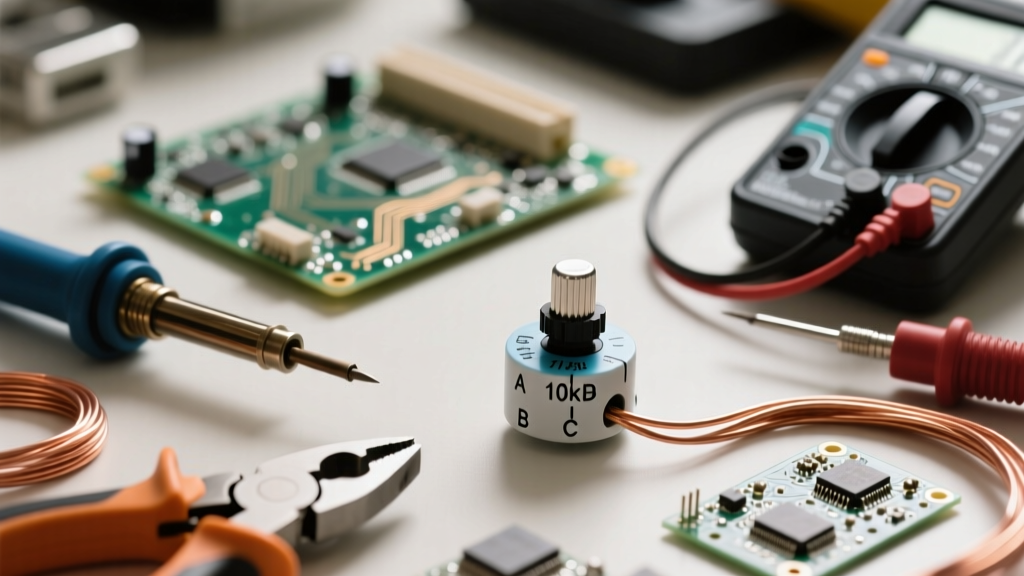
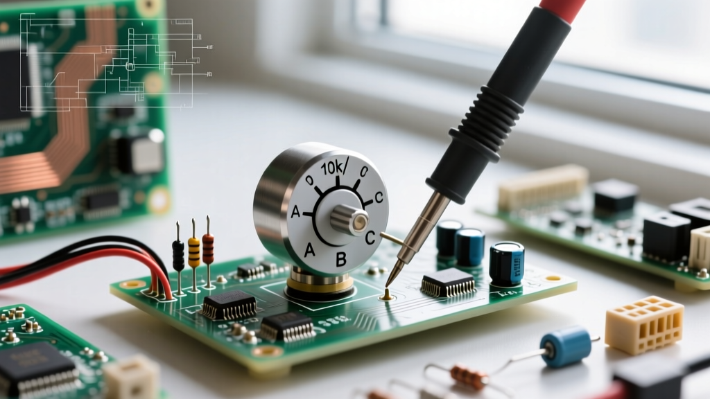
Before connecting your multimeter probes, it is critical to understand the internal mechanics of the component. A potentiometer (often called a 'pot') is fundamentally a three-terminal resistor with a sliding or rotating contact that forms an adjustable voltage divider. When you are figuring out how to measure a potentiometer, you are not just measuring a static block of resistance; you are mapping a physical track and a moving wiper.
The three terminals are universally designated as:
- Terminal 1 (CCW): The counter-clockwise end of the resistive track.
- Terminal 2 (Wiper): The moving contact that sweeps across the track. This is almost always the middle pin on standard through-hole components.
- Terminal 3 (CW): The clockwise end of the resistive track.
The resistive track itself can be manufactured from several materials, including carbon composition, cermet (ceramic and metal), wirewound nichrome, or conductive plastic. Each material dictates not only the component's lifespan and noise floor but also how your digital multimeter (DMM) will interpret its resistance sweep. For a deep dive into the foundational theory of variable resistors, All About Circuits provides an excellent breakdown of how these tracks function in DC circuits.
The In-Circuit Trap: Why Your Readings Might Be Wrong
The most common mistake beginners make when learning how to measure potentiometer resistance is attempting to do so while the component is still soldered to a printed circuit board (PCB). If you place your DMM probes across pins 1 and 3 of a 10kΩ Bourns 3296 trimpot on an active guitar pedal board, you might read 4.7kΩ and assume the pot is defective. It is not.
Because the wiper and the outer lugs are connected to other components (like op-amps, capacitors, or parallel resistors), your multimeter is measuring the equivalent parallel resistance of the entire surrounding network, not just the potentiometer. According to the laws of parallel resistance, the total measured resistance will always be lower than the lowest individual resistor in the network.
Golden Rule of Potentiometer Measurement: To get an accurate reading of the pot's native resistance, you must desolder and lift at least one of the outer legs (Terminal 1 or 3) completely off the PCB pad to isolate it from the circuit.
Step-by-Step Guide: Measuring Total Resistance
To verify the nominal value of the potentiometer (the value printed on the casing, such as 'B10K' or 'A500K'), follow these steps:
- Set your multimeter to the Ohms (Ω) setting. If you are using a manual-ranging DMM, select a range higher than the expected value (e.g., the 20kΩ or 200kΩ range for a 10kΩ pot).
- Place the red probe on Terminal 1 and the black probe on Terminal 3. (Polarity does not matter for resistance measurements).
- Rotate the shaft or turn the adjustment screw fully from one extreme to the other.
Expected Result: The multimeter should display a value within the component's tolerance (typically ±20% for carbon pots and ±10% for cermet trimpots) and, crucially, the reading should not change as you turn the knob. You are measuring the entire length of the static resistive track. If the reading fluctuates wildly or shows 'OL' (Open Loop), the internal track is fractured or the terminal rivets have detached.
Verifying the Taper: Linear (B) vs. Logarithmic (A)
One of the most vital diagnostic skills in electronics prototyping is identifying a pot's taper. The taper defines the relationship between the mechanical rotation of the shaft and the electrical resistance ratio. According to Wikipedia's entry on Potentiometer Tapers, the two most common tapers are Linear (B-taper) and Audio/Logarithmic (A-taper).
Manufacturers often print a letter code on the casing (e.g., B10K is 10kΩ Linear; A10K is 10kΩ Logarithmic). However, vintage parts, unmarked faders, or custom OEM components may lack this coding. Here is how to measure and verify the taper using the 50% Mechanical Center Test.
The 50% Wiper Position Test
First, measure the total resistance across pins 1 and 3 (let's assume it reads exactly 10.0kΩ). Next, carefully rotate the shaft to its exact mechanical midpoint. For a standard 270-degree audio pot, this is 135 degrees; for a multi-turn trimpot like the Bourns 3296, you must count the total turns and divide by two to find the physical center.
Once at the mechanical center, place your probes between Terminal 1 and the Wiper (Terminal 2):
- If the reading is ~5.0kΩ (50% of total): You have a Linear (B) taper. The resistance changes at a constant rate relative to physical movement.
- If the reading is ~1.0kΩ to 2.0kΩ (10% to 20% of total): You have a Logarithmic (A) taper. The resistance curve is shallow at the beginning of the rotation and steep at the end, mimicking the human ear's non-linear perception of volume.
- If the reading is ~8.0kΩ to 9.0kΩ: You likely have an Anti-Log / Reverse-Log (C) taper, often used for specific tone controls or left-channel balance circuits.
Measuring the Wiper and the Voltage Divider Effect
When used in a circuit, a potentiometer acts as a voltage divider. As explained in SparkFun's Voltage Divider Tutorial, the wiper essentially splits the single resistor into two series resistors (R1 and R2). To verify this behavior on your bench:
- Keep the black probe on Terminal 1 and move the red probe to the Wiper (Terminal 2).
- Rotate the knob fully counter-clockwise. The reading should drop to near 0Ω (representing the contact resistance of the wiper resting on the terminal lug, usually less than 5Ω).
- Rotate the knob fully clockwise. The reading should climb to match the total resistance measured earlier (e.g., 10kΩ).
- Now, move the black probe to Terminal 3 while keeping the red probe on the Wiper. The sweep will be inverted: starting at 10kΩ and dropping to near 0Ω.
At any given physical position, the sum of the resistance from Pin 1-to-Wiper and Pin 3-to-Wiper must exactly equal the total track resistance. If Pin 1-to-Wiper reads 4kΩ, Pin 3-to-Wiper must read 6kΩ on a 10kΩ track.
Diagnosing Real-World Failure Modes
Potentiometers are mechanical components, meaning they are subject to physical wear, oxidation, and environmental contamination. Static resistance measurements only tell half the story. To diagnose 'scratchy' audio faders or jittery sensor inputs, you must perform Dynamic Resistance Measurement.
Wiper Noise and Dead Spots
Set your DMM to the lowest Ohms range (or use the continuity beep setting if testing for dead spots). Connect your probes to Terminal 1 and the Wiper. Slowly and steadily rotate the shaft through its entire range while watching the DMM display.
- Dead Spots: If the meter suddenly flashes 'OL' (infinite resistance) or drops out, the carbon track has a physical gap or severe wear at that specific rotational degree. This causes audio dropouts or sudden voltage spikes in microcontroller ADC inputs.
- Wiper Noise (Scratchiness): In carbon composition pots (like the Alpha RD901F), dirt, oxidation, or carbon dust builds up between the wiper finger and the track. While rotating, you will see the resistance jump erratically (e.g., jumping from 2.5kΩ to 8kΩ and back to 2.6kΩ in a split second). This is the exact cause of 'scratchy' volume knobs and can often be temporarily resolved by flushing the casing with specialized contact cleaner like DeoxIT D5.
Track Material Degradation
Wirewound potentiometers (used in high-power applications like motor speed controls) do not suffer from carbon dust, but they suffer from wire wear. As the wiper slides back and forth over the nichrome wire, it can eventually snap the wire, resulting in a permanent open circuit. Cermet trimpots, conversely, are highly resistant to wear but can suffer from moisture ingress, which causes the total resistance (Pins 1 to 3) to slowly drift upward over years of operation in humid environments.
Reference Table: Common Potentiometer Types and Expected Readings
Use this reference guide to anticipate measurement quirks based on the physical construction of the potentiometer you are testing.
| Track Material | Typical Use Case | Measurement Quirks & Failure Modes | Common Models |
|---|---|---|---|
| Carbon Composition | Audio volume, guitar pedals, tone controls | Highly prone to wiper noise and contact resistance spikes. Total resistance can drift with high humidity. | Alpha RD901F, Piher PT15 |
| Cermet | PCB trimmers, sensor calibration, bias adjustment | Extremely stable total resistance. Multi-turn models (25 turns) require careful counting to find the mechanical center for taper testing. | Bourns 3296W, Vishay T73 |
| Wirewound | High-power rheostats, industrial motor controls | Resistance changes in discrete micro-steps rather than a smooth sweep. DMM may show minor 'stair-step' jumps during dynamic testing. | Vishay 534 Series, Beckman 89PR |
| Conductive Plastic | High-end audio mixing faders, precision joysticks | Virtually zero wiper noise. Highly linear resistance sweep. Very low contact resistance (often < 1Ω). | ALPS RS60 Series, Bourns PDB241 |
Summary
Mastering how to measure a potentiometer goes far beyond simply reading the value printed on the back of the casing. By isolating the component from parallel circuit paths, verifying the electrical center to determine the taper, and performing dynamic sweeps to check for wiper noise, you can confidently diagnose, prototype, and repair complex analog circuits. Whether you are biasing a transistor with a cermet trimpot or wiring up an audio mixer with conductive plastic faders, your multimeter is the ultimate tool for mapping the mechanical-to-electrical translation happening inside the component.