
The Hidden Dangers in K Type Thermocouple Wiring Diagrams
When industrial engineers and electricians search for a k type thermocouple wiring diagram, the primary focus is usually on achieving an accurate temperature reading. However, from a safety, electrical code, and process control perspective, an incorrect wiring topology is not merely a measurement error—it is a critical safety hazard. In industrial environments like chemical reactors, heat-treating kilns, and high-pressure boilers, a miswired thermocouple can defeat safety interlocks, blind the Programmable Logic Controller (PLC), and trigger catastrophic thermal runaway events.
The K-type thermocouple, composed of Chromel (Nickel-Chromium) and Alumel (Nickel-Aluminum) alloys, is the most widely used temperature sensor globally due to its broad range (-200°C to +1250°C). Yet, its ubiquity breeds complacency. This guide explores the strict National Electrical Code (NEC) requirements, intrinsic safety barriers, and wiring best practices necessary to ensure your thermocouple installations are both metrologically accurate and legally compliant.
ANSI vs. IEC Color Codes: Avoiding Lethal Polarity Reversals
The most common cause of thermal runaway in industrial furnaces is a polarity reversal stemming from conflicting international color codes. The Seebeck effect, which generates the millivolt signal, is highly dependent on the directional flow of electrons from the positive to the negative leg. If a technician wires an IEC-sourced sensor using ANSI assumptions, the polarity is inverted.
When polarity is reversed, the PLC reads a dropping temperature as the furnace actually heats up. The PID controller responds by pushing the heating elements to a 100% duty cycle, resulting in an uncontrolled temperature spike that can melt the furnace lining or ignite surrounding combustible materials.
Global Color Code Matrix
| Standard | Positive Leg (Alloy) | Negative Leg (Alloy) | Overall Jacket |
|---|---|---|---|
| ANSI MC96.1 (USA) | Yellow (Chromel) | Red (Alumel) | Yellow |
| IEC 60584 (Intl) | Green (Chromel) | White (Alumel) | Green |
| British BS 1041 | Yellow (Chromel) | Blue (Alumel) | Brown |
Field Trick: If you encounter an unmarked or legacy K-type wire, use a rare-earth magnet. The Alumel (negative) leg is slightly magnetic due to its aluminum and manganese content, while the Chromel (positive) leg is non-magnetic. Always verify against the NIST Thermocouple Database before energizing the system.
Wire Grade vs. Extension Grade: A Code Compliance Trap
A frequent code violation found during industrial audits is the substitution of standard copper control wire for thermocouple extension wire. According to the principles of thermoelectricity, any junction between two dissimilar metals creates a parasitic thermocouple. If you use copper wire to extend a K-type sensor to the control panel, you inadvertently create two new cold junctions at the sensor connection head.
While modern transmitters feature Cold Junction Compensation (CJC), the CJC sensor is located inside the transmitter housing, not at the sensor head. The temperature gradient across the copper wire will introduce massive, unpredictable errors. More importantly, NFPA 70 (NEC) requires that instrumentation wiring match the environmental ratings of the circuit. Extension grade wire is rated for lower ambient temperatures (typically 0°C to 200°C) and utilizes cheaper insulation. Using it inside a high-heat kiln zone violates fire safety codes and risks insulation meltdown, leading to short circuits and false zero-millivolt readings (which a PLC might interpret as a safe, cold state).
Grounding, Shielding, and EMI: NEC Article 725 Requirements
Thermocouples generate signals in the microvolt to low millivolt range. Routing a K-type thermocouple cable parallel to Variable Frequency Drives (VFDs) or high-voltage switchgear without proper shielding will induce electromagnetic interference (EMI). This 60Hz noise can easily swamp the 41 µV/°C signal of a K-type sensor, causing the PLC to register erratic temperature spikes and trip nuisance safety shutdowns.
Under NEC Article 725 (Class 1, Class 2, and Class 3 Circuits), instrumentation cables must be adequately shielded and separated from power conductors. When executing your k type thermocouple wiring diagram, adhere to these strict grounding rules:
- Single-Point Grounding: The drain wire of the shielded thermocouple cable must be grounded at the PLC/Transmitter end ONLY.
- Isolate the Sensor End: Never ground the shield at the thermocouple connection head. If both ends are grounded, a difference in ground potential between the motor/furnace and the control room will cause current to flow through the shield. This 'ground loop' induces noise directly into the signal wires via capacitive coupling.
- Grounded vs. Ungrounded Probes: In high-noise environments, a grounded-tip thermocouple (where the junction is physically welded to the metal sheath) provides a Faraday cage effect. However, this requires the entire sheath to be at the same ground potential as the PLC, which is rarely true in industrial plants. For 95% of industrial applications, an ungrounded mineral-insulated (MI) probe paired with a shielded, single-point grounded extension cable is the safest and most code-compliant choice.
Expert Safety Warning: Never use a standard multimeter to check continuity on a grounded thermocouple while the PLC is live. The multimeter's internal battery can inject current back into the PLC's analog input card, permanently damaging the isolated analog-to-digital converter.
Hazardous Locations: Intrinsic Safety Barriers (Class I, Div 1)
When wiring K-type thermocouples in hazardous environments—such as petrochemical refineries or grain elevators classified as Class I, Division 1 under NEC Article 500—standard wiring diagrams are insufficient. You must implement Intrinsic Safety (IS) protocols to ensure the thermocouple circuit cannot release enough thermal or electrical energy to ignite the surrounding atmosphere.
Because thermocouples are passive sensors (they generate their own voltage), they do not require power from the control room. However, the connecting wires can act as antennas, picking up stray RF energy or fault currents from adjacent high-voltage lines. To comply with ATEX, IECEx, and NEC Article 504 standards, a Zener barrier or Galvanic Isolator must be installed in the safe area (control room).
The Zener barrier limits the voltage and current that can travel down the wire into the hazardous area. If a short circuit occurs in the hazardous zone, the barrier's internal fuse blows, and the Zener diodes clamp the voltage, preventing an incendiary spark. When drafting your wiring diagram for hazardous locations, the IS barrier must be placed between the field wiring and the PLC input card, and the barrier's ground terminal must be tied to a dedicated, verified earth ground (less than 1 ohm resistance).
Failure Mode & Code Violation Troubleshooting Matrix
Use this diagnostic matrix to identify hidden code violations and safety risks in existing K-type thermocouple installations.
| Symptom / PLC Reading | Probable Wiring Fault | Safety / Code Implication |
|---|---|---|
| Temp reads exactly ambient (20°C) regardless of process heat. | Short circuit in the extension wire or at the connection head. | PLC reads 0mV (interpreted as 0°C or ambient depending on CJC). High risk of thermal runaway if safety interlocks rely on high-temp trips. |
| Temp reading drops as furnace heats up. | ANSI/IEC color code mismatch; polarity reversed. | Critical Safety Failure. PID controller will overfire the furnace. Violates IEC 61511 safety instrumented system (SIS) logic. |
| Erratic readings fluctuating by ±15°C at 60Hz intervals. | Shield grounded at both ends (ground loop) or routed parallel to VFDs. | Violates NEC Article 725 separation rules. Can cause nuisance tripping of safety shutdown valves. |
| Reading is offset by 10°C - 25°C consistently. | Copper wire used instead of K-type extension wire; parasitic junctions. | Process control degradation. Product quality failure, potential violation of FDA/ASME thermal validation codes. |
Executing the Final Wiring Topology
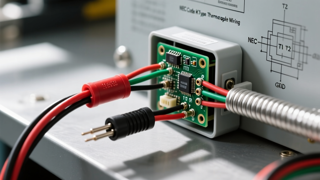
To finalize a safe, code-compliant k type thermocouple wiring diagram, follow this sequence:
- Sensor to Connection Head: Use Thermocouple Grade wire (rated for the full process temperature). Keep leads as short as possible.
- Connection Head to Control Panel: Use Shielded Thermocouple Extension Grade wire. Ensure the ANSI/IEC jacket colors match the sensor leads.
- Shield Management: Terminate the drain wire to the isolated shield ground bar inside the control panel. Trim and heat-shrink the drain wire at the sensor head so it cannot accidentally touch the metal connection head.
- Signal Isolation: For critical safety interlocks (SIS), route the signal through a galvanic isolator before it reaches the PLC analog input card. This protects the PLC from ground surges and lightning strikes on long outdoor cable runs.
For further reading on instrumentation calibration and signal integrity, consult the Fluke Temperature Calibration Guidelines. By treating the thermocouple circuit not just as a sensor, but as a critical safety instrumented loop, you ensure both metrological accuracy and strict adherence to industrial electrical codes.