
The Metallurgy of Soldering Tips: Why Tinning is Non-Negotiable
Setting up a new soldering station involves far more than simply plugging it into a wall outlet and waiting for it to heat up. The most critical step in the initial setup—and the ongoing calibration of your workflow—is understanding how to tin solder iron tips properly. At a microscopic level, modern soldering tips are not solid copper. They consist of a highly conductive copper core encased in a protective iron plating, which is then pre-tinned at the factory. However, this factory tinning is merely a preservative coating designed to prevent shelf oxidation.
When you power on your station for the first time, that preservative layer burns off within seconds. If you fail to immediately apply fresh solder and flux, the exposed iron plating will react with oxygen in the air, forming a layer of iron oxide. This black, crusty layer acts as a severe thermal insulator. A properly tinned tip transfers heat to the solder joint in milliseconds; an oxidized tip will fail to melt solder entirely, leading to cold joints, damaged PCB pads, and frustrated technicians. According to Hakko USA's official tip care guidelines, over 80% of premature tip failures are directly caused by improper initial tinning and subsequent thermal abuse.
Pre-Setup: Calibrating Your Station's Thermal Offset
Before you learn the physical steps of how to tin solder iron components, you must ensure your station's temperature readout matches the actual thermal output at the tip. Budget soldering irons often suffer from a 20°C to 40°C variance between the dial setting and the tip temperature. Even high-end stations with PID (Proportional-Integral-Derivative) controllers can experience thermal lag or require offset calibration if you are using third-party replacement tips.
Understanding PID Controllers and Thermal Lag
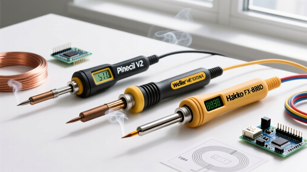
Modern stations like the Hakko FX-888D or the Pinecil V2 utilize embedded thermocouples to monitor tip temperature in real-time. The PID algorithm pulses power to the heating element to maintain a stable thermal equilibrium. However, if you are using a heavy chisel tip for large ground planes, the thermal mass may cause the sensor to read higher than the actual working surface. To calibrate:
- Insert a tip thermometer (such as the Hakko FG-100) or use a high-precision K-type thermocouple taped to the tip with Kapton tape.
- Set your station to 300°C and allow it to stabilize for three minutes.
- Compare the station's digital readout to the physical thermometer.
- Enter your station's calibration menu (often accessed by holding a specific button sequence during boot-up) and apply the necessary positive or negative offset.
Temperature Matrix: Solder Alloy vs. Ideal Tinning Parameters
The temperature required to properly tin your iron depends heavily on the metallurgical composition of the solder wire you are using. Applying excessive heat accelerates the dissolution of the iron plating into the tin, effectively eating away your tip. Use the following calibration matrix to set your baseline temperatures:
| Solder Alloy Type | Composition | Melting Point | Ideal Tinning Temp | Max Continuous Temp |
|---|---|---|---|---|
| Eutectic Leaded | 63/37 SnPb | 183°C (361°F) | 240°C - 270°C | 350°C |
| Lead-Free (SAC305) | 96.5/3/0.5 SnAgCu | 217°C (423°F) | 300°C - 330°C | 380°C |
| High-Temp Leaded | 90/10 SnPb | 268°C (514°F) | 320°C - 340°C | 400°C |
Step-by-Step Tutorial: How to Tin Solder Iron Tips Correctly
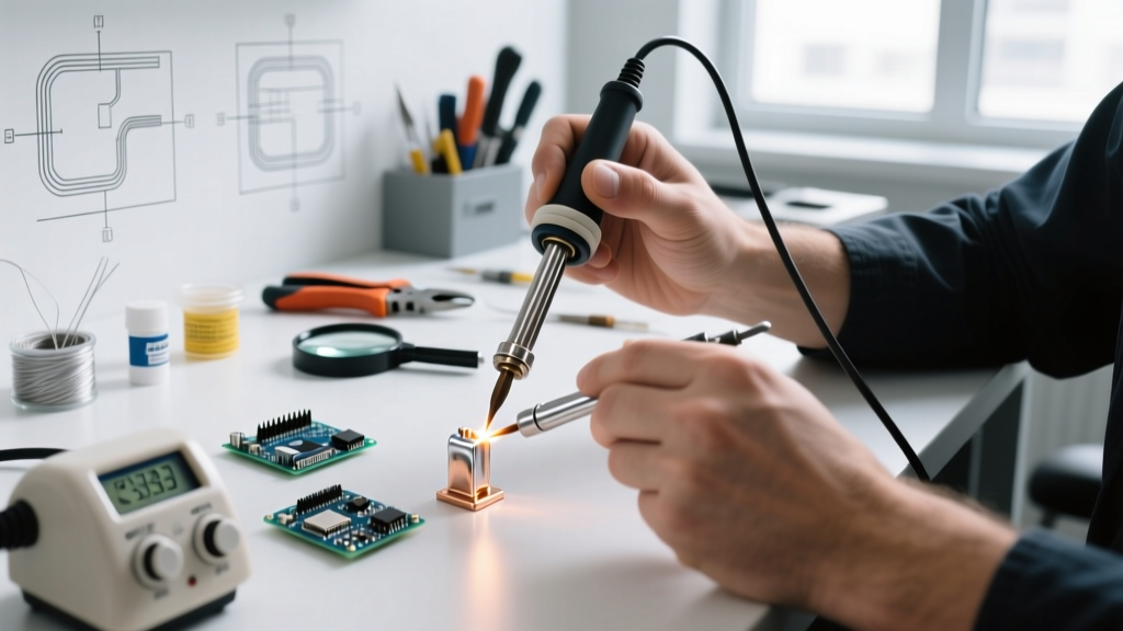
With your station calibrated, you are ready to perform the initial tinning sequence. This process must be executed swiftly the moment the iron reaches its target temperature to prevent flash-oxidation. As detailed in SparkFun's comprehensive soldering tutorial, having your materials staged before turning on the iron is crucial.
Phase 1: Preparation and Staging
- Flux Selection: Use a high-quality Rosin Mildly Activated (RMA) or No-Clean flux paste. Avoid highly acidic plumbing fluxes, which will instantly corrode electronics tips.
- Solder Wire: Have your solder wire unspooled and ready. For initial tinning, a thicker diameter (0.8mm to 1.0mm) with a generous 2% to 3% flux core is ideal.
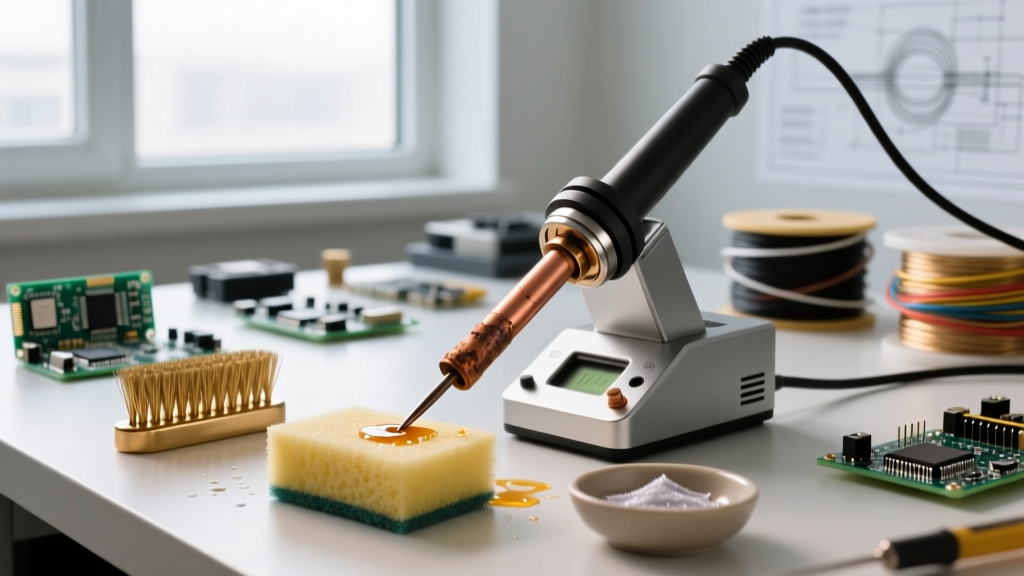
- Cleaning Medium: Prepare your brass wire sponge. Do not use water at this stage.
Phase 2: The Tinning Execution
- Power On: Turn on your station and set it to the lower end of your alloy's tinning range (e.g., 240°C for 63/37 SnPb).
- Pre-Flux the Tip: As the iron heats up, dip the very end of the tip into your flux paste. This creates a protective chemical barrier against oxygen while the iron reaches thermal equilibrium.
- Feed the Solder: The moment the iron is hot enough to melt the solder (you will see the flux bubble and smoke slightly), press the solder wire against all working surfaces of the tip.
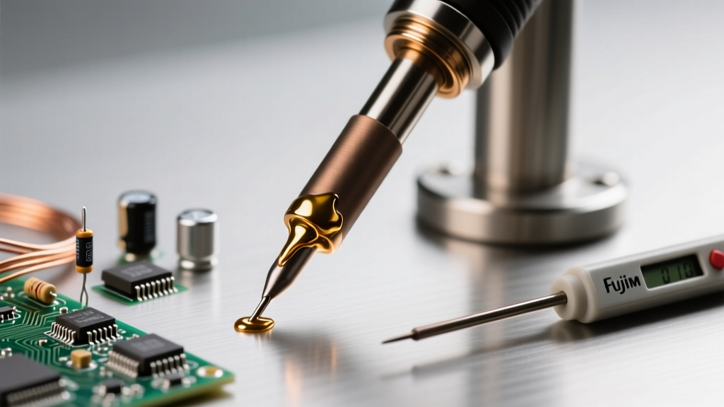
- Rotate and Coat: Rotate the iron to ensure the molten solder wets the entire working area. The solder should flow smoothly, creating a bright, mirror-like finish.
- Wipe and Re-tin: Gently wipe the tip in the brass sponge to remove burnt flux residue, then immediately apply a fresh layer of solder before placing the iron back in its holder.
Daily Operation: Maintaining the Tinned Layer
Knowing how to tin solder iron tips is only half the battle; maintaining that layer during a multi-hour assembly session requires strict discipline. The golden rule of soldering is never leave a bare tip exposed to the air. Whenever you place the iron back into its holster, it must be coated with a thick blob of fresh solder. This sacrificial layer will oxidize instead of the iron plating beneath it.
The Great Debate: Brass Wool vs. Cellulose Sponges
Historically, technicians used damp cellulose sponges to clean tips. However, introducing a 400°C tip to a wet sponge causes rapid thermal shock. This sudden temperature drop can cause micro-fractures in the iron plating, leading to pitting and eventual copper leaching. Brass wire sponges (like the Hakko 599B) are the modern standard. They scrape away oxidized solder and carbonized flux without dropping the tip's core temperature, allowing your PID controller to maintain thermal stability.
Advanced Troubleshooting: Rescuing Oxidized and 'Dead' Tips
Even with meticulous care, tips can become oxidized if left unattended or if exposed to lead-free solder alloys at high temperatures for extended periods. When solder balls up and rolls off the tip like water on a hot skillet, your tip is 'dead' (oxidized). Do not throw it away immediately.
Critical Warning: Never use sandpaper, emery cloth, or a metal file to scrape an oxidized tip. The iron plating is only fractions of a millimeter thick. Abrasives will strip the plating entirely, exposing the copper core, which will dissolve into the solder pool within minutes, permanently destroying the tip.
The Tip Tinner/Activator Protocol
To rescue an oxidized tip, you need a chemical deoxidizer, commonly sold as a 'Tip Tinner' (e.g., Hakko 599B or Amtech Tip Tinner). These compounds contain aggressive activators suspended in a matrix of solder powder.
- Heat your iron to a moderate 300°C.
- Plunge the oxidized tip directly into the tip tinner compound.
- Twist the iron gently for 3 to 5 seconds. You will see smoke and hear a sizzling sound as the activators strip the iron oxide.
- Withdraw the iron and immediately wipe it vigorously in your brass sponge.
- Apply fresh, flux-cored solder wire to re-establish the protective tinned layer.
If the tip remains black after two attempts with a tip tinner, the iron plating has likely been compromised, and the tip must be replaced. For further insights on industry-standard maintenance and workmanship requirements, refer to the IPC J-STD-001 requirements for soldered electrical and electronic assemblies, which heavily emphasize tip maintenance to prevent thermal damage to sensitive components.
Establishing a Long-Term Maintenance Protocol
To maximize the lifespan of your soldering station and ensure consistent thermal transfer, integrate the following calibration and maintenance checks into your lab's standard operating procedures:
- Weekly: Inspect tips under magnification for pitting or erosion. Clean the station's handpiece connector with isopropyl alcohol to ensure accurate PID sensor readings.
- Monthly: Verify the station's thermal offset using a calibrated tip thermometer, especially if multiple technicians share the same equipment and frequently swap tip geometries.
- Annually: Replace the heating element and ceramic enclosure if you notice delayed thermal recovery times, as the thermocouple junction degrades over years of high-temperature cycling.
Mastering how to tin solder iron equipment is the foundational skill that separates amateur hobbyists from professional electronics technicians. By respecting the metallurgy of your tips, calibrating your station accurately, and adhering to strict tinning protocols, you will achieve flawless solder joints and drastically reduce your consumable costs.