
Integrating a reliable gyroscope sensor ESP32 setup is a rite of passage for robotics, drone, and wearable developers. The Espressif ESP32 offers immense processing power with its dual-core 240MHz architecture and native I2C/SPI peripherals, making it an ideal host for motion tracking. However, not all Inertial Measurement Units (IMUs) are created equal. Choosing the wrong sensor can lead to I2C bus lockups, severe thermal drift, or excessive power consumption that ruins battery life.
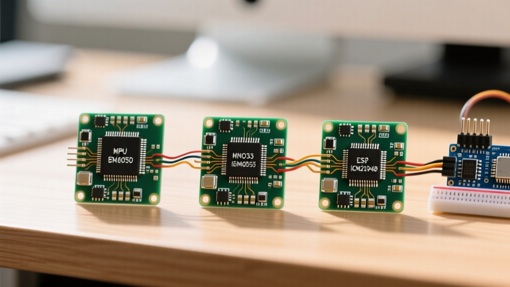
In this comprehensive component comparison, we evaluate the most popular gyroscope and IMU modules compatible with the ESP32 ecosystem. We will dissect the budget-friendly MPU-6050, the premium Bosch BNO055, the modern TDK ICM-20948, and the ultra-low-power BMI160 to help you engineer the perfect motion-tracking peripheral.
The Contenders: Silicon Specifications and Pricing
Before diving into ESP32-specific wiring and firmware constraints, let us establish the baseline hardware specifications. The table below contrasts the four dominant sensors found in maker and commercial prototyping spaces.
| Sensor Model | Axes | Onboard Fusion | Logic Level | Deep Sleep Current | Approx. Price (2024) |
|---|---|---|---|---|---|
| MPU-6050 (TDK/InvenSense) | 6-Axis | No (DMP requires complex firmware) | 3.3V / 5V Tolerant | ~5 μA | $2.00 - $5.00 |
| BNO055 (Bosch) | 9-Axis | Yes (Hardware Cortex-M0) | 3.3V Strict | ~1.2 mA (Standby) | $35.00 - $45.00 |
| ICM-20948 (TDK) | 9-Axis | Yes (DMP supported) | 3.3V Strict | ~8 μA | $15.00 - $22.00 |
| BMI160 (Bosch) | 6-Axis | No | 3.3V Strict | ~3 μA | $8.00 - $12.00 |
ESP32 I2C Wiring and Logic Level Constraints
The most common failure point when pairing a gyroscope sensor ESP32 configuration is ignoring logic level thresholds and I2C pull-up requirements. The ESP32 operates strictly at 3.3V logic. Feeding 5V into GPIO 21 (SDA) or GPIO 22 (SCL) will permanently damage the silicon.
The Pull-Up Resistor Trap
Cheap MPU-6050 breakout boards (often marked with a red or blue PCB) are designed for 5V Arduino Uno environments. They frequently include 10kΩ pull-up resistors tied to a 5V VCC rail. If you wire this directly to an ESP32, the I2C bus will idle at 5V, risking GPIO degradation. Furthermore, the ESP32's internal pull-ups (approximately 45kΩ) are far too weak to support 400kHz Fast Mode I2C.
- Solution for 5V Breakouts: Remove the surface-mount 10k resistors on the breakout board and install external 4.7kΩ or 2.2kΩ pull-up resistors tied to the ESP32's 3.3V pin.
- Solution for Native 3.3V Sensors: Sensors like the BNO055 and ICM-20948 Adafruit breakouts include proper 3.3V regulation and 10kΩ pull-ups to 3.3V. For long wire runs exceeding 15cm, parallel an additional 4.7kΩ resistor to sharpen the I2C rise times.
I2C Address Conflicts
When building multi-sensor ESP32 peripherals (e.g., dual IMUs for differential steering robots), address collisions are inevitable. The MPU-6050 offers only two addresses via the AD0 pin (0x68 and 0x69). The ICM-20948 also toggles between 0x68 and 0x69. If your design requires multiple gyroscopes, you must either utilize an I2C multiplexer like the TCA9548A or leverage the ESP32's secondary hardware I2C bus, mapping it to alternative GPIO pins via the Arduino Wire library.
Sensor Fusion: Offloading the ESP32 Dual-Core CPU
Raw gyroscope data suffers from integration drift over time. To achieve stable Yaw, Pitch, and Roll (Euler angles), you must fuse the gyroscope with the accelerometer and magnetometer. This is where the architectural differences between our contenders drastically impact ESP32 firmware design.
With the MPU-6050 or BMI160, the ESP32 must perform sensor fusion in software. Implementing a Madgwick or Mahony AHRS (Attitude and Heading Reference System) filter on the ESP32 is entirely feasible. At a 200Hz sample rate, a software Madgwick filter consumes roughly 12-15% of a single ESP32 core. While acceptable for simple projects, it introduces latency and jitter if your main loop is interrupted by Wi-Fi or Bluetooth tasks.
Conversely, the Bosch BNO055 contains an internal Cortex-M0 microcontroller dedicated entirely to sensor fusion. It outputs clean, drift-compensated Quaternions or Euler angles directly over I2C. This completely frees the ESP32's CPU cycles for complex kinematics, networking, or display rendering. According to the Bosch BNO055 Datasheet, the onboard fusion algorithm dynamically calibrates the magnetometer in real-time, a process that is notoriously difficult to code manually on the ESP32.
Pro-Tip: When using the BNO055 with an ESP32, always request data in Quaternions rather than Euler angles. Euler angles suffer from Gimbal Lock at ±90 degrees pitch. Convert the Quaternions to Euler angles locally on the ESP32 only when necessary for UI display.
Deep Sleep Integration: Wake-on-Motion (WOM)
Battery-powered ESP32 wearables and asset trackers rely on the chip's Deep Sleep mode, which drops current consumption to roughly 10 μA. However, the ESP32 needs a trigger to wake up. This is where the ICM-20948 and BMI160 shine compared to the BNO055.
Both the ICM-20948 and BMI160 feature a programmable Wake-on-Motion (WOM) interrupt. You can configure the sensor to detect a specific G-force threshold (e.g., a 50mg acceleration spike). When triggered, the sensor pulls its INT pin HIGH.
Wiring the Interrupt to ESP32 RTC GPIOs
To wake the ESP32 from Deep Sleep via an external sensor interrupt, the INT pin must be connected to an RTC-capable GPIO. On the standard ESP32 WROOM module, these are GPIOs 0, 2, 4, 12-15, 25-27, and 32-39.
Recommended Wiring: Connect the IMU INT pin to GPIO 33. Configure the ESP32's esp_sleep_enable_ext0_wakeup() API to trigger on a HIGH signal. This allows a physical tap on the device to wake the ESP32, log GPS data via Wi-Fi, and return to sleep, extending battery life from hours to months.
Real-World Failure Modes and Troubleshooting
Even with perfect wiring, environmental factors and I2C bus quirks can derail your project. Here are the most common failure modes encountered when deploying a gyroscope sensor ESP32 system in the field.
- I2C Bus Lockup: If the ESP32 resets or loses power while the IMU is transmitting a logic LOW, the SDA line can become stuck LOW. The ESP32 will fail to initialize the bus on reboot. Fix: Implement a software I2C bus recovery routine that toggles the SCL pin manually 9 times to release the slave device, or use a hardware watchdog timer.
- Gyroscope Saturation (Clipping): If your ESP32 drone experiences a violent crash or high-vibration motor harmonics, the gyroscope's ADC may max out (e.g., exceeding ±2000°/s). The sensor will output flatlined data, causing the fusion filter to diverge wildly. Fix: Dynamically adjust the Full Scale Range (FSR) via I2C registers, or implement mechanical vibration dampening (sorbothane pads) between the motors and the IMU.
- Thermal Drift: The MPU-6050 is notorious for temperature-dependent bias drift. As the ESP32's onboard voltage regulator heats up the PCB, the gyroscope's zero-rate offset shifts. Fix: Read the onboard temperature sensor register, map the thermal gradient, and apply a software compensation curve to the raw gyro data before feeding it to your AHRS filter.
Decision Matrix: Which Sensor for Which Project?
Selecting the correct component depends entirely on your project's constraints regarding budget, CPU overhead, and power delivery.
- Choose the MPU-6050 if: You are building a budget-conscious educational robot, a simple balancing vehicle, or a prototyping proof-of-concept where CPU overhead is acceptable and extreme precision is not required.
- Choose the BNO055 if: You are developing VR headsets, high-end robotics arms, or indoor navigation rovers where absolute orientation accuracy is paramount, and you want to offload complex quaternion math from the ESP32.
- Choose the ICM-20948 if: You are designing advanced IoT wearables, GPS asset trackers, or low-power drones that require 9-axis tracking, magnetometer integration, and robust Deep Sleep Wake-on-Motion capabilities.
- Choose the BMI160 if: You are engineering ultra-low-power ESP32-C3 or ESP32-S3 smartwatches, fitness trackers, or step-counters where 6-axis data and micro-amp sleep currents are the primary design drivers.
Authoritative References
For deeper register-level programming and ESP32 API integration, consult the following technical documentation:
- Bosch Sensortec: BNO055 Smart Sensor Datasheet (Fusion algorithms and I2C mapping).
- TDK InvenSense: ICM-20948 Product Specifications (DMP firmware and Wake-on-Motion thresholds).
- Espressif Systems: ESP32 Technical Reference Manual (RTC GPIO wake-up sources and I2C peripheral timing).