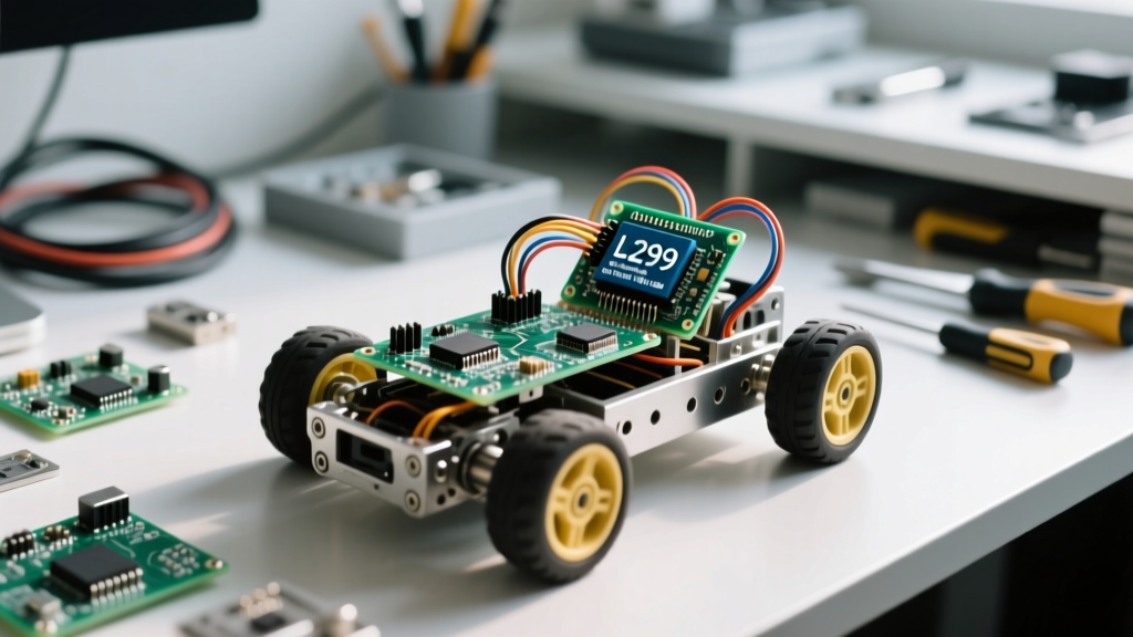

Building your first Arduino robot is a rite of passage for electronics hobbyists and engineering students alike. While the internet is flooded with generic kits and copy-paste code, most beginner guides fail to address the real-world hardware quirks that cause projects to stall, drift, or catch fire. In this comprehensive guide, we will build a 2-Wheel Drive (2WD) differential rover from scratch, focusing on the electrical engineering principles that separate a frustrating paperweight from a reliable autonomous platform.
Why Start with a 2WD Arduino Robot?
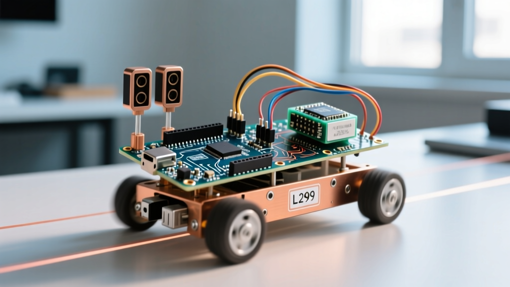
A 2WD differential drive chassis uses two independently driven wheels and a passive caster wheel for balance. This kinematic model is the undisputed best starting point for robotics beginners. Unlike Mecanum or Omni-wheel setups that require complex inverse kinematics and four synchronized motor drivers, a 2WD rover requires only basic logic: spin both wheels forward to move, spin them in opposite directions to turn. This simplicity allows you to focus on mastering motor control, power management, and sensor integration before tackling complex mathematical models.
The Essential Hardware Bill of Materials (BOM)
Selecting the right components is critical. The most common point of failure in beginner robots is inadequate power delivery. Below is a curated BOM designed to avoid the most frequent voltage and current bottlenecks.
| Component | Recommended Model / Spec | Est. Price | Why We Chose It |
|---|---|---|---|
| Microcontroller | Arduino Uno R3 (or Elegoo equivalent) | $22.00 | Standardized pinout, massive community support, and 5V logic. |
| Motor Driver | L298N Dual H-Bridge Module | $6.00 | Handles up to 2A per channel; includes an onboard 5V regulator. |
| Chassis & Motors | Acrylic 2WD Kit with TT Gearmotors | $15.00 | 6V DC motors with 1:48 gear reduction provide excellent low-speed torque. |
| Power Source | 2x 18650 Li-ion Cells + Holder | $12.00 | 7.4V nominal. High current delivery without the voltage sag of AA batteries. |
Understanding the L298N Motor Driver Dropout Voltage
Before wiring anything, you must understand the internal architecture of the L298N. According to the Texas Instruments L298 datasheet, the chip uses bipolar junction transistors (BJTs) arranged in Darlington pairs to switch the motor current. This design results in a significant voltage drop—typically between 2.0V and 3.0V—across the driver.
If you attempt to power your L298N and motors using a 5V USB power bank, the motors will only receive roughly 2.5V. The TT gearmotors will stall, and the Arduino will brownout. This is why we specify a 2S (two-cell) 18650 Lithium-Ion battery pack. A fully charged 2S pack provides 8.4V, which drops to ~7.4V under load. After the L298N's internal voltage drop, your motors still receive a healthy 5V to 6V, ensuring reliable operation.
Step-by-Step Wiring Diagram & Pinout
Proper wiring ensures your microcontroller doesn't get destroyed by back-EMF or ground loops. For a complete pin mapping, always refer to the official Arduino Uno Rev3 documentation. Below is the standard wiring matrix for our 2WD setup:
- 18650 Battery (+) to L298N 12V terminal
- 18650 Battery (-) to L298N GND terminal
- L298N GND to Arduino GND (CRITICAL: Common ground is mandatory)
- L298N 5V Output to Arduino VIN (Powers the Uno, remove the 5V jumper cap if using >12V, but for 8.4V, leave it on)
- L298N IN1 & IN2 to Arduino Digital Pins 8 & 9 (Left Motor Logic)
- L298N IN3 & IN4 to Arduino Digital Pins 10 & 11 (Right Motor Logic)
- L298N ENA & ENB to Arduino PWM Pins 5 & 6 (Speed Control)
Pro-Tip: Never connect the motor power directly to the Arduino's 5V pin. DC motors generate massive electrical noise and back-EMF spikes when reversing direction. The L298N module includes optoisolation and flyback diodes to protect your sensitive logic circuits from these spikes.
Common Beginner Wiring Mistakes (And How to Fix Them)
Even with a perfect schematic, physical wiring often introduces bugs. Here are the top three failure modes encountered by beginners:
- The Missing Common Ground: If you forget to connect the GND of the L298N to the GND of the Arduino, the logic signals (IN1-IN4) will float. The motor driver will behave erratically, often spinning one motor randomly while ignoring your code. Always establish a common ground reference.
- Using 4x AA Alkaline Batteries: A 4x AA holder outputs 6V nominally. However, alkaline batteries have high internal resistance. When the motors start drawing 1A+ of stall current, the voltage sags below 4V, triggering the Arduino's brownout detector and causing endless reboot loops. Stick to Li-ion or high-quality NiMH cells.
- PWM Pin Confusion: Not all digital pins on the Uno support Pulse Width Modulation (PWM). Pins 8, 9, 10, and 11 are standard digital I/O. If you want variable speed control via
analogWrite(), you must wire the ENA and ENB jumpers to pins marked with a tilde (~), such as 5 and 6.
Writing Your First Differential Drive Sketch
Below is a robust, non-blocking C++ sketch to test your wiring. This code defines discrete functions for movement, making it infinitely easier to add ultrasonic sensors or Bluetooth control later. For more on motor control theory, check out the Arduino Motors guide.
// Pin Definitions
const int ENA = 5;   // PWM Left
const int IN1 = 8;   // Logic Left 1
const int IN2 = 9;   // Logic Left 2
const int IN3 = 10;  // Logic Right 1
const int IN4 = 11;  // Logic Right 2
const int ENB = 6;   // PWM Right

void setup() {
  pinMode(ENA, OUTPUT);
  pinMode(ENB, OUTPUT);
  pinMode(IN1, OUTPUT);
  pinMode(IN2, OUTPUT);
  pinMode(IN3, OUTPUT);
  pinMode(IN4, OUTPUT);

  // Ensure motors are stopped on boot
  stopMotors();
}

void loop() {
  moveForward(200);  // Speed 0-255
  delay(2000);
  turnRight(150);
  delay(1000);
  moveBackward(200);
  delay(2000);
  stopMotors();
  delay(3000);
}

void moveForward(int speed) {
  digitalWrite(IN1, HIGH);
  digitalWrite(IN2, LOW);
  digitalWrite(IN3, HIGH);
  digitalWrite(IN4, LOW);
  analogWrite(ENA, speed);
  analogWrite(ENB, speed);
}

void moveBackward(int speed) {
  digitalWrite(IN1, LOW);
  digitalWrite(IN2, HIGH);
  digitalWrite(IN3, LOW);
  digitalWrite(IN4, HIGH);
  analogWrite(ENA, speed);
  analogWrite(ENB, speed);
}

void turnRight(int speed) {
  digitalWrite(IN1, HIGH);
  digitalWrite(IN2, LOW);
  digitalWrite(IN3, LOW);
  digitalWrite(IN4, HIGH);
  analogWrite(ENA, speed);
  analogWrite(ENB, speed);
}

void stopMotors() {
  digitalWrite(IN1, LOW);
  digitalWrite(IN2, LOW);
  digitalWrite(IN3, LOW);
  digitalWrite(IN4, LOW);
  analogWrite(ENA, 0);
  analogWrite(ENB, 0);
}
Calibrating for Straight-Line Drift
You will quickly notice a frustrating reality: when you command your Arduino robot to drive straight, it slowly curves to the left or right. This is not a bug in your code; it is a mechanical reality of cheap manufacturing.
The yellow TT gearmotors included in most beginner kits have wide manufacturing tolerances. Even if both motors receive the exact same PWM value (e.g., 255), one might spin at 190 RPM while the other spins at 205 RPM. Over a distance of two meters, this 15 RPM difference results in a massive deviation from a straight line.
The Software Offset Solution
To fix this without buying expensive encoders, you must introduce a software calibration offset. Place your robot on a chalk line, run it forward at a fixed PWM for 3 seconds, and measure the drift. If it veers left, the right motor is spinning faster. You must reduce the PWM value sent to the right motor.
Modify your moveForward function to include a calibration variable:
int rightMotorOffset = 15; // Reduce right motor PWM by 15

void moveForwardCalibrated(int speed) {
  // ... set logic pins HIGH/LOW ...
  analogWrite(ENA, speed);
  analogWrite(ENB, speed - rightMotorOffset);
}
Iterate on this offset value until your rover tracks straight. This simple calibration step is the hallmark of a well-tuned beginner project.
Upgrading Your Rover: Next Steps
Once your 2WD Arduino robot is reliably rolling, the platform is ready for autonomous upgrades. The most logical next step is mounting an HC-SR04 ultrasonic sensor to the front acrylic plate. By adding a micro-servo (like the SG90), you can create a 'scanning' eye that checks left and right distances before executing a turn, forming the basis of classic obstacle avoidance algorithms.
Alternatively, consider swapping the Arduino Uno for an ESP32. The ESP32 operates at 3.3V logic (requiring a logic level shifter or a 3.3V compatible motor driver like the TB6612FNG), but it unlocks Wi-Fi and Bluetooth telemetry, allowing you to stream battery voltage and motor speeds to a custom web dashboard in real-time.