
The Sensor-First Philosophy in DIY Robotics
Most beginner robotics projects rely on open-loop control—sending a pulse-width signal to a servo and hoping it reaches the destination. When you transition into serious robotics, from scratch to 5-axis DIY robot arm designs, this approach quickly falls apart. Inertia, payload variations, and mechanical backlash introduce cumulative errors that render open-loop systems useless for precision tasks. The solution is a sensor-driven architecture. By integrating closed-loop stepper motors, Time-of-Flight (ToF) spatial awareness, and inertial measurement units (IMUs) for master-slave telemetry, we transform a collection of 3D-printed plastics and aluminum into a responsive, intelligent manipulator.
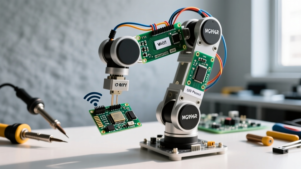
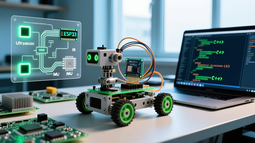
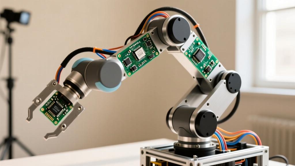
This guide details the engineering, wiring, and programming required to build a 5-Degree-of-Freedom (5-DOF) robotic arm powered by an ESP32-S3, focusing heavily on the sensory feedback loops that separate hobby toys from functional automation.
Bill of Materials: Sourcing the 5-Axis Skeleton
Building a robust arm requires balancing torque, weight, and resolution. Standard SG90 micro-servos lack the holding torque for a 5-axis payload, while NEMA 23 steppers are too heavy for the distal joints. We use a hybrid approach: high-torque closed-loop steppers for the base and shoulder, and lightweight smart servos for the wrist.
| Component | Model / Specification | Qty | Est. Cost (USD) | Purpose |
|---|---|---|---|---|
| Microcontroller | ESP32-S3-WROOM-1 (Dual-Core) | 1 | $8.00 | Master kinematics & sensor polling |
| Base/Shoulder Motors | BigTreeTech S42B V2.0 (Closed-Loop NEMA 17) | 3 | $135.00 | Joints 1-3 (High torque, zero homing) |
| Wrist Motors | Feetech SCS15 Smart Servos | 2 | $40.00 | Joints 4-5 (Compact, serial bus) |
| Proximity Sensor | STMicroelectronics VL53L1X ToF Breakout | 1 | $12.00 | End-effector object detection |
| Master Controller | MPU6050 IMU + Flex Sensors (Glove) | 1 | $15.00 | Gesture and spatial mapping |
| Power Supply | Mean Well LRS-350-24 (24V 15A) | 1 | $45.00 | Main logic and motor bus |
| Chassis | 2020 V-Slot Aluminum + PETG 3D Prints | 1 | $60.00 | Structural rigidity |
Why Closed-Loop Steppers Change the Game
The BigTreeTech S42B V2.0 features an integrated magnetic encoder on the rear shaft. Unlike standard steppers that blindly consume current and skip steps if overloaded, the S42B's onboard PID controller reads the encoder 10,000 times per second. If the arm encounters an unexpected payload or collision, the motor increases current to maintain position or triggers a fault flag via UART to the ESP32-S3. This eliminates the need for physical limit switches and homing routines, drastically simplifying the mechanical design of the 5-axis DIY robot arm.
Wiring the Nervous System: ESP32-S3 and I2C Topology
Routing sensor data through a moving, multi-axis arm is a notorious point of failure. The VL53L1X Time-of-Flight sensor on the gripper communicates via I2C. However, I2C was designed for on-board communication, not for running through 1.5 meters of moving cable harnesses next to high-current stepper wires.
According to Texas Instruments application notes on I2C bus design, the maximum allowable bus capacitance is 400pF. Long, unshielded cables running parallel to stepper motor phases will induce electromagnetic interference (EMI), causing phantom clock pulses and bus lockups.
Pro-Tip: Never run I2C lines parallel to motor phases. Use a shielded CAT6 Ethernet cable for the end-effector sensor run. Dedicate one twisted pair to SDA, one to SCL, and tie the shield to the chassis ground at the ESP32 end only to prevent ground loops. Use 2.2kΩ pull-up resistors on the master side to ensure sharp signal rise times.
For the Feetech SCS15 wrist servos, we utilize a half-duplex TTL serial bus (Robotis Dynamixel protocol compatible). The ESP32-S3's hardware UART2 handles this, requiring only a single data wire connected to the servos in a daisy-chain topology, complete with a 120-ohm termination resistor at the final gripper servo to prevent signal reflection.
Implementing the VL53L1X Time-of-Flight Gripper Feedback
The end-effector is equipped with a custom 3D-printed parallel gripper driven by a rack-and-pinion mechanism. To prevent the arm from crushing delicate objects, the VL53L1X ToF sensor is mounted between the gripper fingers, facing inward. As the fingers close, the sensor measures the exact distance to the target object.
By configuring the VL53L1X to "Medium Distance Mode" with a 20ms timing budget, we achieve millimeter-level resolution. The ESP32-S3 polls the sensor via I2C. When the distance delta between consecutive polls drops below 0.5mm, the microcontroller registers that the object has been grasped and immediately halts the wrist servo, engaging its holding torque. This sensor-driven feedback loop allows the arm to pick up both a solid wooden block and a fragile plastic cup using the exact same motion script.
Calibrating the MPU6050 Master Glove
Controlling a 5-axis arm via joysticks is unintuitive. Instead, we build a master-slave telemetry glove. The MPU6050 IMU mounted on the back of the hand tracks pitch, roll, and yaw. However, raw accelerometer data is incredibly noisy due to hand tremors.
We implement a Madgwick AHRS (Attitude and Heading Reference System) filter on the ESP32-S3 to fuse the accelerometer and gyroscope data. This provides a drift-free, smooth quaternion output that is then converted into Euler angles. These angles are mapped to the base and shoulder joints, allowing the operator to control the arm's orientation simply by moving their wrist.
Overcoming the "Jitter Bug": Power and Signal Isolation
When scaling up to a 5-axis system, power distribution becomes critical. The BTT S42B steppers can draw up to 2A per phase, while the ESP32-S3 and sensors require clean 3.3V logic. If powered from the same buck converter, the back-EMF from the steppers will cause brownouts, resetting the microcontroller mid-motion.
- Motor Bus: Fed directly from the 24V Mean Well PSU, buffered by a 4700µF electrolytic capacitor bank to absorb inductive spikes.
- Logic Bus: An isolated DC-DC converter (like the B0505S-2WR3) steps down 24V to 5V, followed by an AMS1117-3.3 LDO for the ESP32 and sensors.
- Opto-isolation: The UART lines connecting the ESP32 to the closed-loop steppers are routed through high-speed optocouplers (e.g., 6N137) to completely break electrical continuity between the noisy motor drivers and the sensitive logic core.
Final Assembly and Inverse Kinematics Tuning
With the hardware assembled and sensor noise mitigated, the final hurdle is software: Inverse Kinematics (IK). IK is the mathematical process of calculating the joint angles required to place the end-effector at a specific X, Y, Z coordinate in 3D space. For a 5-DOF arm, we utilize Denavit-Hartenberg (DH) parameters to model the linkages.
As detailed in the ROS2 TF2 transformation tutorials, managing coordinate frames is essential for spatial awareness. While we aren't running full ROS on the ESP32, we borrow the concept of transformation matrices. The ESP32-S3's dual-core architecture allows Core 0 to handle the heavy floating-point matrix math for the IK solver, while Core 1 manages the I2C polling, UART serial commands, and the Madgwick filter for the master glove.
By combining closed-loop positional certainty, ToF spatial awareness, and isolated power architectures, this sensor-driven approach proves that building professional-grade robotics from scratch to 5-axis DIY robot arm completion is entirely achievable on a workbench. The key is respecting the physics of the sensors and the electrical realities of the environment they operate in.