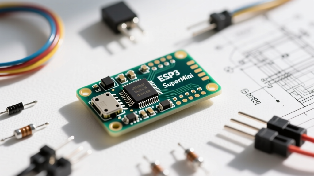

The ESP32 SuperMini has rapidly become a favorite among makers and IoT engineers due to its incredibly compact footprint, low cost, and robust wireless capabilities. However, its diminutive size often leads to confusion regarding its exact pin mappings, strapping pin behaviors, and power limitations. Whether you are designing a custom PCB or wiring up a breadboard prototype, understanding the exact esp32 supermini pinout is critical to avoiding hardware damage and firmware upload failures.
This quick reference guide and FAQ is designed to give you immediate, actionable data on the ESP32-C3 SuperMini variant—the most common board carrying the "SuperMini" moniker—while addressing the most frequent troubleshooting hurdles encountered in the field.
Quick Reference: ESP32 SuperMini Pinout Map
The standard ESP32-C3 SuperMini exposes 14 GPIO pins alongside power and ground rails. Below is the definitive pinout map based on the official Espressif ESP32-C3 Datasheet and community-verified board schematics.
| Silk Label | GPIO Number | Primary Function | Special Notes & Constraints |
|---|---|---|---|
| 5V | VBUS | 5V Power Input | Connect to USB 5V or external regulated 5V supply. |
| GND | GND | Ground | Common ground for all peripherals and power. |
| 3V3 | 3V3 | 3.3V Output/Input | Output from onboard LDO. Can accept regulated 3.3V to bypass LDO. |
| TX | GPIO21 | UART0 TX | Used for serial debugging. Do not pull low on boot. |
| RX | GPIO20 | UART0 RX | Used for serial debugging and firmware flashing. |
| 10 | GPIO10 | General I/O / SPI SS | Safe for general use. Defaults HIGH on reset. |
| 9 | GPIO9 | Strapping Pin | BOOT MODE: Pull to GND during reset to enter serial bootloader. |
| 8 | GPIO8 | Strapping Pin | Connected to internal SPI Flash. Do not use for external peripherals. |
| 7 | GPIO7 | General I/O | Safe for general use, PWM, and I2C. |
| 6 | GPIO6 | General I/O | Safe for general use, PWM, and I2C. |
| 5 | GPIO5 | General I/O | Safe for general use. Supports JTAG if configured. |
| 4 | GPIO4 | ADC1_CH4 / I2C SDA | 12-bit SAR ADC. Safe for analog sensor readings. |
| 3 | GPIO3 | ADC1_CH3 | 12-bit SAR ADC. Safe for analog sensor readings. |
| 2 | GPIO2 | ADC1_CH2 / I2C SCL | 12-bit SAR ADC. Safe for analog sensor readings. |
| 1 | GPIO1 | ADC1_CH1 | 12-bit SAR ADC. Safe for analog sensor readings. |
| 0 | GPIO0 | ADC1_CH0 | 12-bit SAR ADC. Safe for analog sensor readings. |
Note: GPIO18 (USB D-) and GPIO19 (USB D+) are routed directly to the USB-C connector for native USB serial/JTAG and are generally not broken out to the side headers on the SuperMini footprint.
Core Hardware Specifications & Board Variants
When searching for the esp32 supermini pinout, it is vital to confirm which silicon is actually on your board. The vast majority of boards labeled "SuperMini" utilize the ESP32-C3FH4 chip. This is a single-core RISC-V 32-bit processor clocked at 160 MHz, featuring 4MB of embedded Flash and 400KB of SRAM. It supports Wi-Fi 4 (802.11 b/g/n) and Bluetooth 5 (LE).
However, some manufacturers have begun releasing ESP32-S2 or ESP32-S3 boards in identical form factors. The S2/S3 variants feature Xtensa LX7 cores and native USB OTG, but their pinouts differ drastically from the C3. Always verify the silicon printing on the RF shield or use the Arduino IDE's "Get Board Info" tool to confirm the chipset before wiring high-voltage peripherals.
Power Delivery & Voltage Tolerances
The ESP32-C3 SuperMini is a 3.3V logic device. Applying 5V directly to any GPIO pin (including RX, TX, and ADC pins) will permanently damage the silicon. The board includes an onboard Low Dropout Regulator (LDO)—typically an ME6211C33 or AMS1117-3.3—to step down the 5V USB VBUS to 3.3V.
- Maximum LDO Current: If your board uses the ME6211C33, the maximum continuous current draw from the 3V3 pin is roughly 500mA. If it uses an AMS1117, it can theoretically handle 800mA, but the tiny PCB footprint lacks the copper pour necessary for thermal dissipation, leading to thermal shutdown.
- Peripheral Power Budget: When using the onboard 5V-to-3.3V LDO, limit your external 3.3V peripheral draw to 300mA to maintain safe operating temperatures.
- Bypassing the LDO: If you are powering the board from a regulated 3.3V source (like a LiPo battery with a boost/buck converter), inject power directly into the
3V3pin and leave the5Vpin disconnected. This prevents the LDO from generating excess heat or draining quiescent current.
Frequently Asked Questions (FAQ)
How do I force the SuperMini into bootloader/flash mode?
This is the most common issue reported on the Arduino ESP32 Core Repository issue tracker. To save space, the SuperMini omits a physical BOOT button. If the Arduino IDE fails to upload your sketch and times out waiting for packet headers, follow this exact hardware sequence:
- Connect a jumper wire from GPIO9 to GND.
- Plug the USB-C cable into your computer (or press the RESET button if your specific clone has one).
- Wait for the IDE to show "Connecting...".
- Remove the jumper wire from GPIO9 to GND.
- The ESP32-C3 will now boot into the serial bootloader, and the upload will proceed normally.
Which pins support ADC and PWM?
Unlike the original dual-core ESP32, which suffered from severe ADC non-linearity and WiFi-induced noise on ADC2, the ESP32-C3 features a highly stable 12-bit SAR ADC tied to ADC1. You can safely use GPIO0, GPIO1, GPIO2, GPIO3, and GPIO4 for analog readings without WiFi interference dropping your accuracy.
For PWM (LEDC), every digital GPIO (excluding strapping pins 8, 9, and USB pins 18, 19) supports hardware PWM via the Arduino ledc API. For standard I2C, the community standard is to map SDA to GPIO4 and SCL to GPIO2, though the C3 allows software remapping to almost any pin.
Can I use the SuperMini for battery-powered deep sleep?
The ESP32-C3 silicon is capable of an incredibly low deep sleep current of roughly 5µA. However, the SuperMini development board is not optimized for ultra-low power out of the box. The onboard LDO, USB-C port protection diodes, and power indicator LED will draw a combined quiescent current of 50µA to 2mA.
If you are building a battery-operated sensor node that must last for months, you must physically desolder the power LED and its current-limiting resistor, and ideally bypass or remove the onboard LDO, powering the 3V3 rail directly from an ultra-low quiescent current external regulator.
Common Wiring Mistakes & Troubleshooting
When integrating the ESP32 SuperMini into larger circuits, keep these failure modes in mind to protect your hardware and ensure stable operation:
- Strapping Pin Interference: GPIO8 and GPIO9 dictate the boot mode and flash voltage. If you wire external sensors to GPIO9 and that sensor pulls the pin LOW during power-up, the ESP32 will enter bootloader mode and your sketch will not run. Always ensure GPIO9 is pulled HIGH via a 10kΩ resistor if used for peripheral input.
- I2C Pull-up Resistors: The ESP32-C3 internal pull-ups are approximately 45kΩ, which is too weak for reliable high-speed I2C communication. Always add external 4.7kΩ pull-up resistors to the 3.3V rail when wiring SDA and SCL lines to sensors like the BME280 or MPU6050.
- Antenna Clearance: The SuperMini features a PCB trace antenna on the top edge of the board. Do not mount the board flat against a metal enclosure or place copper pours directly beneath the antenna area on your custom carrier board, as this will detune the RF matching network and severely reduce Wi-Fi and BLE range.
For deeper technical specifications regarding the RISC-V architecture and memory mapping, refer to the official ESP-IDF Hardware Reference. By respecting the specific electrical limits and strapping pin behaviors outlined in this esp32 supermini pinout guide, you can confidently deploy these tiny microcontrollers into robust, production-ready IoT environments.