
The Core Translation: Logic Levels to 3-Phase Power
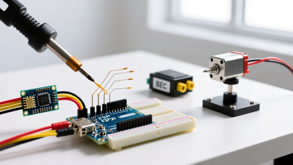
When makers first attempt to interface a high-power brushless DC (BLDC) motor with a microcontroller, they quickly hit a physical wall: an Arduino Uno R3 or Nano outputs 5V logic signals capable of sourcing roughly 20mA to 40mA. A typical 2212 size brushless drone motor requires 11.1V to 14.8V and can draw upwards of 20A under load. The ESC speed controller Arduino setup bridges this massive gap. The Electronic Speed Controller (ESC) acts as a high-current 3-phase inverter, translating the microcontroller's low-voltage timing pulses into the precise, high-amperage AC-like waveforms required to spin the motor's stator electromagnets.
Understanding this relationship is not just about copying and pasting code; it requires grasping the underlying communication protocols, power distribution architectures, and timing constraints that govern modern motor control. In 2026, while digital protocols like DShot dominate the FPV drone racing scene, standard 50Hz Pulse Width Modulation (PWM) remains the bedrock for general robotics, RC vehicles, and DIY Arduino projects due to its universal compatibility and simplicity.
Protocol Deep Dive: 50Hz PWM vs. Digital Alternatives
To control an ESC, the Arduino must send a continuous stream of pulses. The standard hobby ESC expects a 50Hz signal, meaning a new pulse is sent every 20 milliseconds (ms). The width of the high-voltage portion of that pulse dictates the throttle position.
- 1000µs (1ms): Zero throttle (motor stop or idle).
- 1500µs (1.5ms): Mid-throttle (often the arming threshold).
- 2000µs (2ms): Full throttle (100% duty cycle).
While analog PWM is reliable, it is susceptible to electrical noise and lacks bidirectional telemetry. Digital protocols encode the throttle value into binary data packets, eliminating signal jitter and allowing the ESC to send RPM and temperature data back to the MCU.
| Protocol | Signal Type | Refresh Rate / Speed | Resolution | Telemetry Support |
|---|---|---|---|---|
| Standard PWM | Analog Pulse | 50Hz (20ms period) | ~1000 steps | No |
| Oneshot125 | Analog Pulse | Up to 500Hz | ~1000 steps | No |
| DShot600 | Digital Packet | 37.5kHz per bit | 2048 steps (11-bit) | Yes (via separate wire) |
Source: For a comprehensive breakdown of digital packet structures, refer to Oscar Liang's DSHOT Protocol Guide, which remains the industry-standard reference for digital ESC telemetry and timing.
Power Architecture: BEC vs. Opto-Isolated Designs
A critical concept when wiring an ESC to an Arduino is understanding how the microcontroller gets its 5V power. ESCs generally fall into two hardware categories:
1. BEC-Equipped ESCs (Battery Eliminator Circuit)
Most standard hobby ESCs, such as the widely available Hobbywing Skywalker 40A (typically priced between $25 and $32 in 2026), feature a built-in BEC. The BEC steps down the main LiPo battery voltage (e.g., 11.1V from a 3S pack) to a stable 5V to power the Arduino and the ESC's internal optocoupler. Warning: Standard linear BECs dissipate excess voltage as heat. If you are running a 4S (14.8V) or 6S (22.2V) battery and drawing more than 1A from the 5V rail (e.g., powering an Arduino Nano, a servo, and an LED strip), the linear BEC will overheat and trigger thermal shutdown, killing power to your MCU mid-flight or mid-operation.
2. Opto-Isolated ESCs (OPTO)
High-end or high-voltage ESCs (like the DYS XSD series) often omit the BEC entirely to save weight and prevent high-voltage noise from bleeding into the logic circuit. They use optical isolators to separate the high-current motor side from the low-voltage signal side. If you use an OPTO ESC, the red wire on the signal lead provides no power. You must supply 5V to the Arduino from a separate UBEC (Universal Battery Eliminator Circuit) or a dedicated voltage regulator.
The Grounding Imperative and Wiring Matrix
The Golden Rule of Motor Control: A signal is only as good as its ground reference. If the Arduino's GND and the ESC's GND are not tied together, the PWM signal will float, resulting in erratic motor spasms or complete failure to arm.
Below is the standard wiring matrix for connecting a typical 3-wire ESC signal lead to an Arduino Uno R3 or Nano (ATmega328P architecture).
| ESC Signal Wire | Arduino Pin | Function & Notes |
|---|---|---|
| White / Yellow (Signal) | Digital Pin 9 | PWM Output. Must use a hardware timer pin. |
| Red (5V BEC) | 5V Pin | Powers the Arduino. Disconnect if using external 5V source. |
| Black / Brown (GND) | GND Pin | Common ground reference. Absolutely mandatory. |
The Calibration Handshake: Why Your Motor Beeps and Refuses to Spin
A common point of frustration for beginners is uploading a sketch, sending a 2000µs pulse, and hearing the ESC emit a series of error beeps instead of spinning the motor. This is because modern ESCs feature a safety lock and require endpoint calibration to account for slight timing variances in different microcontroller crystals.
The calibration handshake forces the ESC to learn exactly what your specific Arduino considers 'zero' and 'full' throttle. Here is the conceptual flow of the calibration process:
- Step 1: Power the Arduino and command a 2000µs (full throttle) PWM signal.
- Step 2: Connect the main LiPo battery to the ESC. The ESC will read the high pulse and enter programming mode (usually indicated by a specific musical tone or double beep).
- Step 3: Immediately command a 1000µs (zero throttle) signal. The ESC reads the low endpoint, confirms with a final beep, and stores the 1000-2000µs range in its EEPROM.
- Step 4: Disconnect the battery. Your ESC is now calibrated to your Arduino's specific timer output.
For exact button-press sequences and tone interpretations, always consult the specific manufacturer's documentation, such as the Arduino Servo Library Documentation for generating the precise microsecond pulses required for this handshake.
Edge Cases: Jitter, Brownouts, and Desyncs
When moving from a bench test to a functional robot or vehicle, several real-world failure modes emerge. Understanding these will separate a novice tinkerer from an embedded systems engineer.
1. Signal Jitter from Blocking Code
The standard Servo.h library in the Arduino IDE hijacks Timer1 on the ATmega328P to generate the precise 50Hz interrupt required for ESC control. If your main loop uses blocking functions like delay() or poorly timed millis() polling that interferes with interrupt service routines (ISRs), the PWM pulse width will jitter. A jitter of just 10µs can cause a sensitive ESC to interpret the signal as 'unstable' and refuse to arm. Solution: Keep the main loop non-blocking and avoid using pins 9 and 10 for analogWrite() when Servo.h is active, as they share Timer1.
2. Voltage Brownouts on Motor Startup
Brushless motors draw massive current spikes (often 30A+) during the initial startup phase. If your battery has high internal resistance or your wiring is too thin, this spike causes a voltage sag. If the sag drops the main battery voltage low enough, the ESC's internal BEC will momentarily drop below 4.5V, causing the Arduino Nano or Uno to brownout and reset. Solution: Solder a low-ESR 470µF 25V electrolytic capacitor directly across the 5V and GND pins on your Arduino's power header to act as a local energy reservoir during startup transients.
3. The 3.3V Logic Threshold (Arduino Uno R4 & ESP32)
While classic 5V Arduinos output a clean 5V HIGH signal, newer boards like the Arduino Uno R4 Minima or ESP32 operate on 3.3V logic. Older or cheaper ESC optocouplers require a minimum of 4.0V to reliably register a 'HIGH' pulse. If you interface a 3.3V MCU directly to a 5V-threshold ESC, the motor will simply ignore the signal. Solution: Use a bidirectional logic level converter (like the Texas Instruments TXS0108E) or a simple MOSFET-based level shifter to boost the 3.3V PWM signal to a solid 5V before it reaches the ESC signal wire.
Summary
Mastering the ESC speed controller with Arduino requires looking past the basic wiring diagram. By understanding the 50Hz PWM timing architecture, respecting the thermal limits of linear BECs, ensuring common ground references, and accounting for logic-level thresholds on modern 3.3V microcontrollers, you can build robust, high-power motor control systems that operate reliably in the real world.