
The Brains and the Brawn: Why Combine Them?
Integrating a microcontroller with a single-board computer is a staple architecture in advanced maker projects. When you select an Arduino for Pi deployments, you are pairing the high-level processing, networking, and Linux environment of the Raspberry Pi with the deterministic, real-time, and analog-friendly I/O of an Arduino. Whether you are building a CNC controller, a multi-sensor environmental station, or a robotic arm, the Pi handles the computer vision and MQTT routing while the Arduino manages the stepper motors and ADC readings.
However, bridging these two ecosystems is not as simple as plugging in a few jumper wires. Hardware incompatibilities—specifically regarding logic levels and bus capacitance—can instantly destroy your Raspberry Pi's SoC. This guide provides a deep-dive compatibility matrix, board recommendations, and critical wiring protocols to ensure your hybrid system survives and thrives.
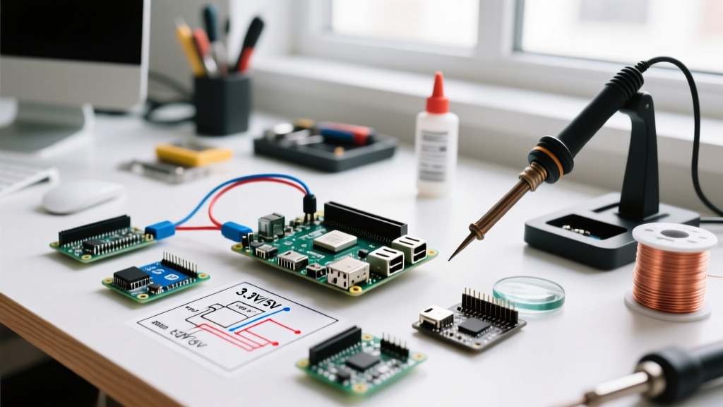
The Voltage Divide: 3.3V vs 5V Logic
The most critical point of failure when connecting an Arduino to a Raspberry Pi is the logic level voltage. All modern Raspberry Pi models (Pi 3, Pi 4, Pi 5, and Zero 2 W) utilize the BCM2837, BCM2711, or BCM2712 SoCs, which feature strictly 3.3V GPIO logic. Applying 5V to any Pi GPIO pin will likely destroy the pin's protection diode and permanently damage the processor.
Critical Warning: Never connect a 5V Arduino digital output directly to a Raspberry Pi GPIO input. Even if the Pi is powered off, back-feeding 5V through a GPIO pin can fry the SoC upon boot.
Classic boards like the Arduino Uno R3 and Nano (ATmega328P based) operate at 5V. To use them with a Pi, you must use a bidirectional logic level converter (such as a BSS138 MOSFET-based module, costing around $1.50) or a dedicated IC like the TXS0108E. Alternatively, you can select a modern Arduino that natively operates at 3.3V, eliminating the need for level shifters entirely.
Communication Protocol Compatibility Matrix
Choosing the right protocol depends on your data throughput requirements and latency tolerance. Below is a compatibility and performance matrix for Pi-Arduino bridging.
| Protocol | Max Speed | Wiring Complexity | Level Shifting Required? | Best Use Case |
|---|---|---|---|---|
| USB Serial | 2 Mbps | Low (1 Cable) | No (Handled by USB IC) | Telemetry, Firmata, debugging |
| UART (TX/RX) | 115.2 kbps | Low (2 Wires + GND) | Yes (If 5V Arduino) | Low-latency command streaming |
| I2C (SDA/SCL) | 400 kHz | Medium (2 Wires + GND) | Yes (If 5V Arduino) | Multi-node sensor polling |
| SPI (MOSI/MISO) | 10+ MHz | High (4+ Wires) | Yes (If 5V Arduino) | High-speed data (displays, ADCs) |
Top Arduino Boards for Pi Integration
When selecting the ideal Arduino for Pi projects in 2026, native 3.3V tolerance and advanced peripherals take priority over legacy 5V boards.
1. Arduino Uno R4 Minima / WiFi (The Modern Standard)
Powered by the Renesas RA4M1 (Arm Cortex-M4), the Uno R4 series operates at 3.3V logic, making it inherently safe for direct I2C and SPI connection to a Raspberry Pi. The WiFi variant ($27.50) includes an ESP32-S3 coprocessor, allowing the Pi to offload network tasks to the Arduino via internal serial bridging. It also features a true 12-bit DAC and a 14-bit ADC, vastly outperforming the classic Uno's 10-bit resolution.
2. Arduino Nano 33 IoT (The Space-Constrained Choice)
Using the SAMD21 Cortex-M0+ processor, this board runs natively at 3.3V. Priced around $18.00, it is exceptionally reliable for I2C slave configurations where the Pi acts as the master. Its compact footprint allows it to be mounted directly onto Pi HAT prototyping boards. According to the official Arduino Nano 33 IoT documentation, the board includes an onboard IMU and crypto chip, reducing the need for external sensors.
3. Classic Arduino Uno R3 (The Legacy Workaround)
If you must use a classic 5V Uno R3 ($15.00 for clones, $27.00 for official), you must implement hardware level shifting for any direct GPIO, UART, I2C, or SPI connections. The only exception is USB Serial, as the ATmega16U2 USB-to-Serial chip handles the voltage translation internally.
Deep Dive: The I2C Pull-Up Resistor Conflict
The most common silent failure in Pi-Arduino I2C integration is bus capacitance and pull-up resistor conflicts. This is an edge case that ruins signal integrity and causes intermittent data corruption.
The Raspberry Pi's hardware I2C bus (GPIO 2 and GPIO 3) features onboard 1.8kΩ pull-up resistors tied to the 3.3V rail. You can verify your specific Pi model's GPIO layout using the interactive Pinout database. When you connect a 3.3V Arduino (like the Nano 33 IoT) to this bus, the Arduino's Wire.h library does not enable internal pull-ups by default, which is good. However, if you are using a breakout board or shield on the Arduino side that includes its own 4.7kΩ pull-up resistors, the parallel resistance drops.
Combining a 1.8kΩ (Pi) and 4.7kΩ (Arduino shield) resistor results in a total pull-up resistance of roughly 1.3kΩ. While a stronger pull-up helps overcome bus capacitance, it also increases the current sink required by the devices. If the combined sink current exceeds the 3mA limit of the Pi's GPIO pins, the logic 'LOW' voltage will float above the 0.8V threshold, causing the Pi to misread data as 'HIGH'.
Actionable I2C Wiring Steps
- Disable Redundant Pull-ups: Physically remove or cut the trace to any 4.7kΩ pull-up resistors on the Arduino-side sensor shields if the Pi is acting as the master.
- Wire the Bus: Connect Pi GPIO 2 (SDA) to Arduino SDA. Connect Pi GPIO 3 (SCL) to Arduino SCL.
- Common Ground: Connect Pi GND to Arduino GND. Never skip this step, even if both boards are powered by the same USB hub, to prevent ground loops.
- Set Bus Speed: In your Raspberry Pi Python script (using
smbus2), force the I2C baud rate to 100 kHz (standard mode) rather than 400 kHz (fast mode) to ensure signal stability across the physical bridge.
Software Bridging: Firmata vs. Custom Serial
Once the hardware is safely connected, the software architecture dictates your system's responsiveness.
The Firmata Approach
StandardFirmata allows the Raspberry Pi to control the Arduino's pins directly using Python libraries like pyFirmata. This is excellent for rapid prototyping. The Pi sends hex commands over USB Serial, and the Arduino executes them. However, Firmata introduces a 3ms to 8ms latency per command due to serial parsing overhead. It is unsuitable for high-speed PID motor control or precise PWM generation.
Custom UART / JSON Payloads
For production environments, write a custom C++ sketch for the Arduino that outputs structured JSON over a hardware UART connection (using a logic level shifter). The Pi runs a Python daemon using pyserial to read the stream. This offloads the timing-critical loops to the Arduino's bare-metal environment while allowing the Pi to parse complex JSON payloads for database logging and cloud synchronization.
Power Supply Considerations and Ground Loops
A frequent failure mode occurs when makers attempt to power the Arduino directly from the Raspberry Pi's 5V GPIO pins. The Pi's 5V rail is tied directly to the USB-C power input. An Arduino Uno R4 can draw up to 150mA at idle, and significantly more when driving relays or servos. Drawing more than 200mA from the Pi's 5V GPIO pins risks tripping the Pi's polyfuse or causing brownouts that reboot the Linux OS.
The Solution: Use a shared, high-capacity 5V buck converter (rated for at least 3A) to power both the Raspberry Pi (via the GPIO 5V pins or USB-C) and the Arduino (via the 5V or VIN pin). Ensure all grounds are tied together at a single star-point to prevent ground loops, which can introduce noise into the Arduino's ADC readings.
Summary
Selecting the correct Arduino for Pi integration hinges on respecting the 3.3V logic boundary and understanding I2C bus physics. By opting for native 3.3V boards like the Uno R4 or Nano 33 IoT, utilizing proper UART level shifters for legacy boards, and managing pull-up resistor parallel loads, you create a robust, industrial-grade hybrid system capable of handling both high-level networking and microsecond-precision hardware control.