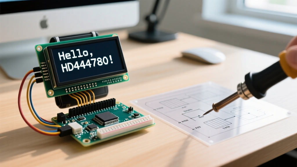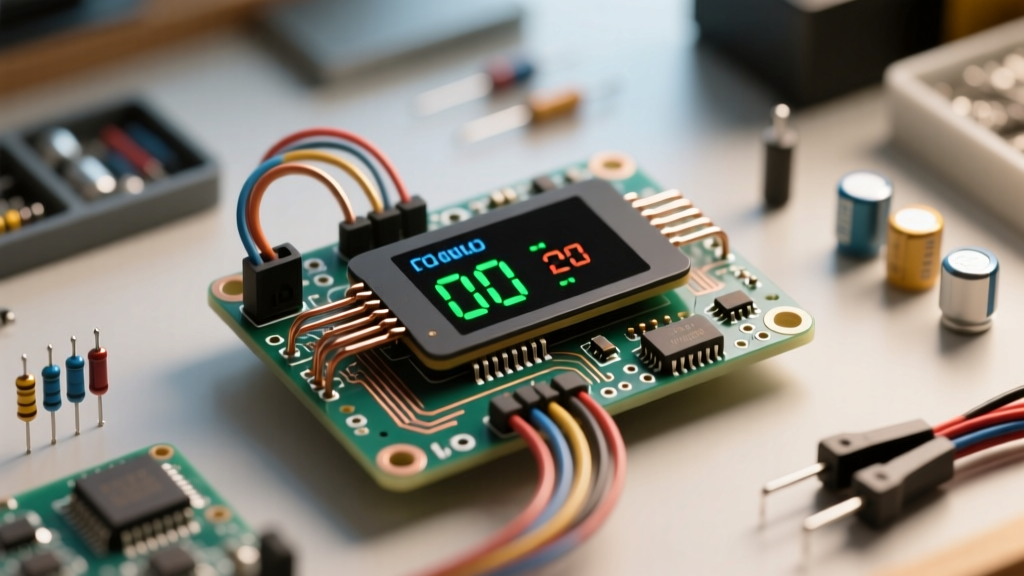

Integrating a local visual interface into your microcontroller projects transforms abstract serial monitor data into actionable, real-time insights. When building environmental monitors, power meters, or IoT edge nodes, the most reliable and power-efficient choice is a display Arduino OLED configuration. Specifically, the 0.96-inch 128x64 I2C OLED driven by the SSD1306 controller has become the undisputed standard for DIY sensor dashboards due to its low cost, high contrast, and minimal wiring requirements.
However, moving from a simple 'Hello World' text print to a fully integrated, multi-sensor dashboard introduces significant architectural challenges. Memory constraints on standard ATmega328P boards, I2C bus conflicts, and non-blocking code requirements can quickly derail a project. This tutorial provides a deep-dive, expert-level guide to wiring, programming, and troubleshooting an OLED sensor dashboard.
The Anatomy of an SSD1306 Module and the SH1106 Trap
Before wiring your display Arduino OLED circuit, you must verify the controller IC. While the market is flooded with cheap 0.96-inch 128x64 I2C OLEDs advertising the SSD1306 chip, many manufacturers secretly substitute the SH1106 controller to cut costs or manage supply chain shortages.
The SH1106 is designed for 132x64 displays. If you drive an SH1106 module using standard SSD1306 libraries, your display will function, but the image will be offset by 2 to 4 pixels to the right, and the left edge of your sensor data will be clipped. Always run an I2C scanner or a specialized test sketch to confirm the controller before finalizing your dashboard UI layout.
I2C vs. SPI: Why I2C Wins for Sensor Nodes
While SPI OLEDs offer faster refresh rates (crucial for rendering complex animations or oscilloscope waveforms), I2C is vastly superior for static sensor dashboards. An I2C OLED requires only two data pins (SDA and SCL), leaving your microcontroller's limited GPIO pins free for integrating DHT22 temperature sensors, BME280 environmental modules, or analog voltage dividers.
Wiring the Display Arduino OLED Circuit
The standard 4-pin I2C OLED breakout is straightforward to wire, but power delivery requires careful attention. Most cheap 'blue backpack' OLED modules feature an onboard 3.3V linear regulator and logic level tolerance, allowing them to be powered directly from a 5V Arduino Uno or Nano.
| OLED Pin | Arduino Uno/Nano | Arduino Pro Mini (3.3V) | Function |
|---|---|---|---|
| GND | GND | GND | Common Ground Reference |
| VCC | 5V | 3.3V | Power Input (Module Regulator) |
| SCL | A5 | A5 | I2C Clock Line |
| SDA | A4 | A4 | I2C Data Line |
Voltage Logic Warning and Pull-Up Resistors
A common hardware failure mode in mixed-voltage sensor networks is I2C bus degradation. The SSD1306 chip operates natively at 3.3V. While the 5V logic from an Arduino Uno's A4/A5 pins usually won't instantly destroy the OLED's I2C interface, it violates the absolute maximum ratings of the silicon. For long-term reliability, especially in industrial or outdoor sensor enclosures, use a bidirectional logic level shifter (like the BSS138) between the 5V Arduino and the 3.3V OLED SDA/SCL lines.
Furthermore, the I2C bus requires pull-up resistors. Most OLED modules include 10kΩ surface-mount pull-ups on the SDA and SCL lines. If you are daisy-chaining multiple sensors (e.g., a BME280 and an OLED on the same bus), the parallel resistance may drop too low, causing signal reflections and data corruption. Monitor your bus with an oscilloscope or logic analyzer; if the rise times are too slow, remove the pull-ups from the OLED module.
Essential Libraries and SRAM Bottlenecks
The most critical hurdle in building a display Arduino OLED sensor dashboard is managing the ATmega328P's severely limited 2048 bytes of SRAM. Rendering a 128x64 monochrome screen requires a framebuffer of exactly 1024 bytes (128 * 64 / 8). If you use the ubiquitous Adafruit SSD1306 library, this 1KB buffer is allocated immediately, consuming 50% of your available memory before you even initialize your sensors.
Library Comparison: Adafruit_SSD1306 vs. U8g2
When integrating multiple sensors, you will quickly run out of memory for Strings, arrays, and sensor libraries. Here is how the two dominant libraries compare for complex dashboards:
| Feature | Adafruit SSD1306 | U8g2 (by olikraus) |
|---|---|---|
| Memory Footprint | High (Requires 1KB contiguous SRAM) | Low (Supports page-buffering mode) |
| Font Support | Limited bitmap fonts | Hundreds of scalable vector fonts |
| Rendering Speed | Fast (Full buffer) | Slower in page mode, fast in full buffer |
| Best Use Case | Simple text readouts, basic shapes | Complex UI, graphs, memory-constrained nodes |
For advanced sensor dashboards featuring sparkline graphs or multiple UI pages, the U8g2 library is highly recommended. Its 'page buffer' mode renders the display in slices, requiring only a fraction of the SRAM while still allowing you to draw complex sensor data visualizations.
Sensor Integration: Non-Blocking Dashboard Architecture
Beginners often use delay() to time their sensor readings and screen updates. In a multi-sensor environment, blocking the main loop for 2 seconds to wait for a DHT22 temperature reading will freeze your OLED UI, making buttons unresponsive and halting background telemetry transmissions.
Implementing a millis() State Machine
To build a professional-grade display Arduino OLED interface, you must decouple sensor polling from screen rendering. Use a millis() based state machine. Poll your I2C sensors every 2000ms, update the internal variables, and run the OLED rendering loop independently every 100ms to ensure smooth UI transitions.
Here is the conceptual architecture for a non-blocking sensor dashboard:
unsigned long lastSensorRead = 0;
unsigned long lastScreenUpdate = 0;
float currentTemp = 0.0;

void loop() {
  unsigned long currentMillis = millis();

  // 1. Poll Sensors (Non-Blocking)
  if (currentMillis - lastSensorRead >= 2000) {
    lastSensorRead = currentMillis;
    currentTemp = readBME280Temperature();
  }

  // 2. Render UI (Independent Framerate)
  if (currentMillis - lastScreenUpdate >= 100) {
    lastScreenUpdate = currentMillis;
    renderDashboardUI(currentTemp);
  }
}
This architecture ensures that your I2C Wire library calls for the sensors do not interfere with the I2C transmission of the framebuffer to the OLED, preventing bus lockups.
Hardware Failure Modes and Troubleshooting
Even with perfect code, physical and electrical realities can cause your OLED dashboard to fail. Keep this troubleshooting framework in mind when debugging your sensor node:
- I2C Address Conflicts (0x3C vs 0x3D): Most 0.96-inch OLEDs default to the I2C address
0x3C. However, some 1.3-inch SH1106 modules or specific SSD1306 variants use0x3D. If your screen remains black, run an I2C scanner sketch. If you are using a BME280 sensor (which also defaults to 0x76 or 0x77), ensure no address collisions are pulling the bus low. - FPC Ribbon Cable Tearing: The Flexible Printed Circuit connecting the glass OLED panel to the PCB is incredibly fragile. If you mount the display in a 3D-printed enclosure, never apply pressure to the glass bezel. A micro-tear in the FPC will result in dead pixel columns or a completely blank screen.
- OLED Screen Burn-In: Unlike LCDs, OLEDs suffer from permanent phosphor degradation. If your sensor dashboard displays static text labels (e.g., 'TEMP:' or 'HUMIDITY:') in the exact same pixel locations 24/7, those pixels will dim permanently within a few months. Implement a 'screen saver' that turns off the display via
display.ssd1306_command(SSD1306_DISPLAYOFF)after 5 minutes of sensor inactivity, or shift the UI layout by a few pixels every hour. - White Noise / Snow on Screen: If your OLED displays random static or 'snow' upon boot, it is usually caused by I2C bus noise during the microcontroller's power-on reset phase. Add a 100nF decoupling capacitor directly across the VCC and GND pins of the OLED module to stabilize the power rail during initialization.
By respecting the electrical limits of the I2C bus, managing your ATmega328P's SRAM intelligently, and utilizing non-blocking code structures, your display Arduino OLED setup will evolve from a simple hobbyist readout into a robust, professional sensor dashboard.