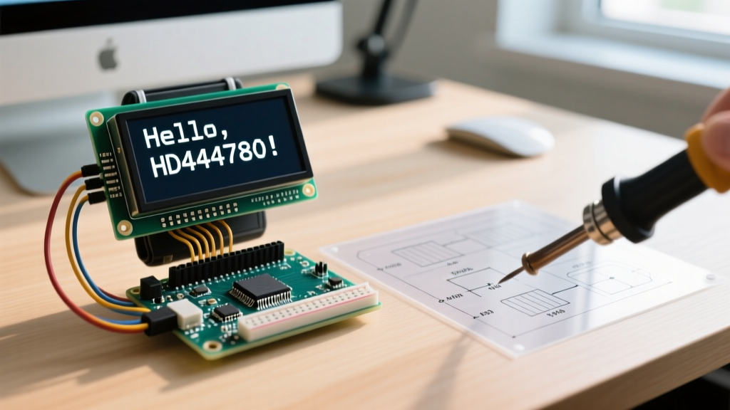

Decoding the HD44780: The Silicon Brain Behind Your Display
Most online tutorials treat character displays as simple plug-and-play peripherals. They tell you to wire up a 16x2 screen, include a library, and call lcd.print(). But when you are coding lcd arduino projects for robust commercial applications, environmental monitors, or complex DIY instrumentation, blindly trusting high-level abstractions leads to timing bugs, I2C bus lockups, and flickering text. To write truly optimized firmware, you must understand the silicon driving the glass: the Hitachi HD44780U controller.
In 2026, the standard 1602A parallel LCD module remains a staple in electronics, costing roughly $3.50, while I2C-equipped variants add about $1.20 for the backpack. Despite the rise of OLEDs and TFTs, the HD44780's low power consumption (typically 2mA for the logic, plus backlight current) and extreme temperature resilience keep it relevant. This datasheet explainer bridges the gap between the raw semiconductor specifications and practical Arduino C++ implementation.
Timing Constraints: What the Datasheet Actually Says
The most common cause of 'garbage characters' or unresponsive displays in custom firmware is violating the HD44780's internal timing constraints. The controller operates on a strict clock cycle, and sending data faster than its internal RAM can latch will result in dropped bytes.
| Datasheet Parameter | Symbol | Minimum Time | Arduino Coding Implication |
|---|---|---|---|
| Enable Pulse Width | tPW | 450 ns | Digital I/O toggling on a 16MHz AVR takes ~62ns per instruction. You must add a brief delay or dummy read to ensure the 'E' pin stays HIGH long enough. |
| Data Setup Time | tDS | 195 ns | Data pins (D4-D7) must be stable before the Enable pin drops. Standard Arduino digitalWrite() handles this naturally due to function call overhead. |
| Standard Instruction Execution | tC | 37 μs | Never spam commands in a loop() without checking the Busy Flag (BF) or inserting a 40μs delay. |
| Clear Display / Return Home | tC | 1.52 ms | Calling lcd.clear() blocks the MCU for over 1.5 milliseconds. Overwriting text with spaces is often faster for real-time UI updates. |
The 4-Bit vs 8-Bit Mode Dilemma
The HD44780 supports an 8-bit parallel bus, but the datasheet explicitly details a 4-bit mode that multiplexes data over pins D4 through D7. In modern microcontroller design, saving four GPIO pins is almost always worth the slight overhead of sending two nibbles per byte. When coding lcd arduino interfaces, the LiquidCrystal library defaults to 4-bit mode. If you are writing bare-metal register code for an ATmega328P, you must sequence the upper nibble first, pulse the Enable pin, then send the lower nibble and pulse again.
The Boot Sequence: Translating Datasheet Initialization
One of the most misunderstood sections of the HD44780 datasheet is the initialization sequence. The controller's internal RAM is in an undefined state when power is first applied. The datasheet mandates a highly specific 'wake-up' sequence to force the chip into a known state, especially when operating in 4-bit mode.
The 3-Step Wake-Up Protocol:
1. Wait at least 15ms after VCC reaches 4.5V.
2. Send0x03(Function Set) and wait 4.1ms.
3. Send0x03again and wait 100μs.
4. Send0x03a third time.
5. Finally, send0x02to lock the controller into 4-bit mode.
If you are using the standard Arduino library, this is handled in the constructor. However, if you are integrating an LCD into a low-power sleep-wake system where the MCU resets but the LCD remains powered, skipping this sequence will cause the display to lock up or default to 8-bit mode, resulting in shifted, corrupted text. According to the Arduino LiquidCrystal Reference, re-initializing the object is required if power to the display was cycled independently of the microcontroller.
The I2C Backpack Shift: PCF8574 Integration
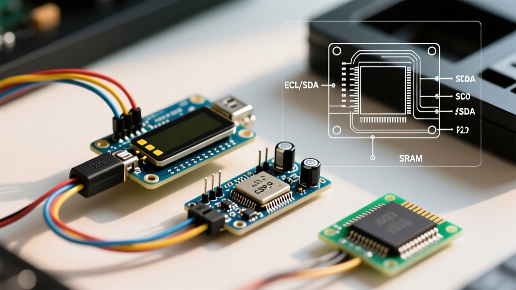
Wiring 12 separate pins for a parallel LCD is obsolete for most hobbyist and prototyping workflows. Today, the market is dominated by I2C backpacks based on the NXP PCF8574 or Texas Instruments PCF8574A I/O expanders. These chips convert the I2C serial protocol into the parallel signals the HD44780 requires.
Real-World I2C Address Matrix
A frequent stumbling block when coding lcd arduino projects with I2C backpacks is address conflicts. The PCF8574 and PCF8574A have different base addresses, determined by the A0, A1, and A2 jumper pads on the PCB.
| Chip Variant | Base Address (Hex) | Address Range (All Pads) | Common Default (Pads Open) |
|---|---|---|---|
| PCF8574 (NXP) | 0x20 | 0x20 to 0x27 | 0x27 |
| PCF8574A (TI/NXP) | 0x38 | 0x38 to 0x3F | 0x3F |
Expert Tip: Always run an I2C scanner sketch before hardcoding addresses in your production firmware. Furthermore, while many cheap backpacks include 10kΩ pull-up resistors on the SDA and SCL lines, these are often too weak for bus runs longer than 30cm. If your display freezes randomly, soldering 4.7kΩ pull-up resistors directly to the I2C header will stabilize the bus capacitance.
Mastering CGRAM: Designing Custom Characters
The HD44780 features 64 bytes of Character Generator RAM (CGRAM), allowing you to define up to eight custom 5x8 pixel glyphs. This is essential for creating battery indicators, signal bars, or custom progress arrows that the standard ASCII ROM lacks.
- Map the Grid: Define an 8-byte array. Each byte represents a row. The lower 5 bits control the pixels (1 = ON, 0 = OFF).
- Write to CGRAM: Use the library's
createChar()function, assigning an ID from 0 to 7. - Render to DDRAM: Print the custom character to the Display Data RAM using its assigned byte ID.
When designing these glyphs, remember that the 8th row (index 7) is often used for the cursor underline. If you enable the hardware cursor, it will overwrite the bottom row of your custom character. To avoid this, design custom icons using only the top 7 rows, or disable the hardware cursor and draw your own software-based cursor indicators.
Hardware Edge Cases & Troubleshooting
Software can only do so much if the hardware interface is flawed. Here are the most common physical failure modes encountered when deploying HD44780 modules in the field:
- The V0 Contrast Trap: Pin 3 (V0) controls the liquid crystal bias voltage. The datasheet specifies that optimal contrast requires V0 to be roughly 0.4V to 0.6V relative to ground. Most tutorials suggest a 10kΩ potentiometer. In reality, a fixed 1kΩ or 1.5kΩ resistor tied between V0 and GND provides perfect contrast for 5V modules, eliminating the mechanical failure point of a cheap potentiometer.
- Backlight Current Limiting: Pins 15 (LED+) and 16 (LED-) power the backlight. While some modern modules include a surface-mount current-limiting resistor on the PCB, many generic 1602A boards do not. Always place a 10Ω to 22Ω resistor in series with the 5V backlight supply to prevent burning out the LED array, which typically draws between 80mA and 120mA.
- Ghosting and Temperature Drift: Liquid crystals are highly temperature-dependent. If your project operates in an unheated garage or outdoor enclosure, the fixed resistor on V0 will fail as ambient temperatures drop, causing 'ghosting' (all pixels turning dark). For wide-temperature deployments, use a thermistor-based voltage divider on the V0 pin to dynamically adjust the contrast bias as the environment changes.
By treating the LCD not just as a screen, but as a memory-mapped peripheral governed by strict semiconductor timing, you elevate your firmware from fragile hobbyist code to robust, production-ready engineering. For deeper hardware integration, reviewing the SparkFun LCD Hookup Guide and the NXP PCF8574 Datasheet will provide the necessary electrical schematics to design your own custom I2C backpacks from scratch.