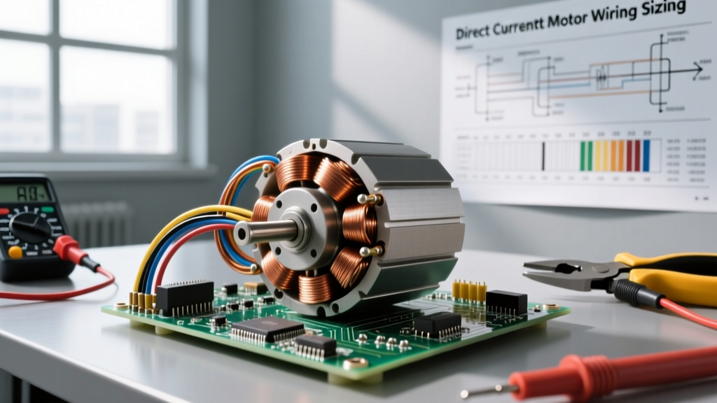

The Electromagnetic Core: How DC Motors Convert Energy
When engineers and DIYers ask what is direct current motor technology, they are usually looking beyond the basic textbook definition. At its core, a DC motor is an electromechanical transducer that converts direct electrical energy into mechanical rotation. However, in real-world applications—ranging from 12V marine winches to 48V electric vehicle (EV) drivetrains—understanding the internal mechanics is only half the battle. The true challenge lies in properly sizing the conductors, managing voltage drop, and mitigating the unique fire risks associated with DC arcing.
Unlike alternating current (AC) systems, where the current periodically reverses direction, a DC motor relies on a unidirectional flow of electrons. This current passes through the stator (the stationary magnetic field) and the armature or rotor (the rotating winding). According to Lorentz force principles, the interaction between the magnetic field and the current-carrying conductors generates torque. As the armature spins, it also generates a counter-voltage known as Back-EMF (Electromotive Force), which naturally limits the current draw as the motor reaches its operational speed. For a deeper dive into the physics of this interaction, HyperPhysics at Georgia State University provides an excellent foundational breakdown of DC motor magnetic fields.
Real-World DC Motor Classifications
Selecting the right wire gauge and overcurrent protection requires knowing exactly which type of DC motor you are wiring. The inrush current and operational profiles vary wildly between the following classifications:
- Permanent Magnet DC (PMDC): Common in automotive applications (wipers, power seats) and small robotics. They use permanent magnets for the stator field. They offer high starting torque but can suffer from demagnetization if subjected to extreme thermal overload or excessive reverse-EMF spikes.
- Series-Wound DC Motors: The stator and rotor windings are connected in series. These are the heavy lifters of the DC world, used in traction applications like forklifts and golf carts. They produce massive starting torque but can experience dangerous "runaway" speeds if the mechanical load is completely removed while powered.
- Shunt-Wound DC Motors: The field winding is in parallel with the armature. These provide excellent speed regulation under varying loads, making them ideal for industrial conveyor belts and machine tools.
- Brushless DC (BLDC): BLDC motors eliminate the mechanical commutator and carbon brushes, relying instead on solid-state electronic speed controllers (ESCs) and Hall-effect sensors. While more expensive, they offer superior efficiency, longer lifespans, and require significantly less maintenance.
The Critical Role of Wire Sizing in Low-Voltage DC
In the "Wire Sizing & Electrical Fundamentals" domain, the most common mistake hobbyists and junior technicians make is treating 12V or 24V DC wiring the same as 120V AC wiring. Because Power (Watts) = Voltage × Current, a low-voltage DC system must pull significantly higher amperage to deliver the same wattage as a high-voltage AC system. This high current makes voltage drop the primary enemy of DC motor performance.
If you undersize your conductors, the resistance of the wire will consume a portion of the supply voltage before it ever reaches the motor terminals. A 12V motor receiving only 9V due to wire resistance will draw more current to compensate for the missing power, leading to thermal runaway, melted insulation, and eventual motor burnout.
Calculating Voltage Drop and Conductor Ampacity
To properly size your wire, you must calculate the one-way distance from the power source to the motor and factor in the maximum continuous current draw. The standard formula for single-phase DC voltage drop is:
VD = (2 × K × I × L) / CM
Where:
VD = Voltage Drop
K = Specific Resistance (12.9 for Copper at 75°C)
I = Current in Amps
L = One-way length of the wire in feet
CM = Circular Mils of the conductor
For most real-world DC motor applications, the National Electrical Code (NEC) and general engineering best practices recommend keeping voltage drop below 3% for branch circuits to ensure optimal motor torque and efficiency. The Engineering Toolbox offers extensive data on DC motor efficiencies and current draws that can help you establish your baseline 'I' variable for this formula.
DC Motor Wire Sizing Reference Chart (12V & 24V Systems)
The following table provides a practical baseline for sizing copper conductors (THHN or high-strand-count silicone) for DC motors, maintaining a maximum 3% voltage drop. Always verify against local codes and the motor manufacturer's Locked Rotor Amps (LRA) specifications.
| Motor Max Current (Amps) | 12V System (Max 10 ft run) | 12V System (Max 25 ft run) | 24V System (Max 15 ft run) | 24V System (Max 40 ft run) |
|---|---|---|---|---|
| 10A | 14 AWG | 10 AWG | 16 AWG | 12 AWG |
| 20A | 10 AWG | 6 AWG | 12 AWG | 8 AWG |
| 40A | 6 AWG | 2 AWG | 8 AWG | 4 AWG |
| 80A | 2 AWG | 2/0 AWG | 4 AWG | 1 AWG |
| 150A+ | 1/0 AWG | 4/0 AWG | 1 AWG | 2/0 AWG |
Note: For robotics or mobile applications where wires are subjected to constant vibration and flexing, always use high-strand-count silicone wire rather than standard solid-core or low-strand THHN, which will work-harden and snap over time.
Overcurrent Protection: The DC Arc Challenge
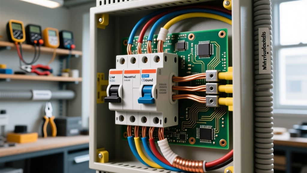
Sizing the wire is only step one; protecting it is step two. When wiring a DC motor, you cannot simply use standard AC circuit breakers. This is a critical safety fundamental that is often overlooked in DIY solar and EV conversions.
Alternating current crosses the zero-voltage point 120 times per second (in a 60Hz system). When an AC breaker trips under a heavy load, this zero-crossing naturally helps extinguish the electrical arc that forms between the separating contacts. Direct current, however, maintains a constant polarity and never crosses zero. When a standard AC breaker attempts to interrupt a high-amperage DC fault, the resulting arc can sustain itself, melt the breaker housing, and cause a catastrophic electrical fire.
According to NFPA 70 (NEC) Article 430, motor circuits require specific overcurrent protection tailored to the motor's Full Load Amps (FLA) and Locked Rotor Amps (LRA). For DC applications, you must use breakers specifically rated for DC voltage (often marked with a "DC" rating and featuring internal magnetic blowouts or arc chutes designed to stretch and cool the DC arc until it extinguishes). Alternatively, use high-interrupting-capacity (AIC) Class T or ANL fuses, which are widely considered the gold standard for high-current DC motor protection in marine and automotive environments.
Field Troubleshooting and Failure Modes
Even with perfectly sized conductors and proper DC-rated fuses, DC motors operate in harsh environments and are subject to specific mechanical and electrical failure modes. Understanding these will save you hours of diagnostic time:
- Commutator Mica Undercutting: In brushed motors, the insulating mica between the copper commutator bars must be slightly lower than the copper surface. If the mica protrudes (due to uneven wear), the carbon brushes will bounce, causing severe arcing, pitting, and eventual ring-fire across the commutator.
- Brush Spring Tension Loss: Over time, the constant thermal cycling and mechanical vibration can weaken the brush springs. Weak springs lead to poor electrical contact, increasing the resistance at the brush face. This localized heat can melt the flexible copper pigtail wire connecting the brush to the external circuit.
- Thermal Runaway in BLDC ESCs: While the BLDC motor itself is robust, the Electronic Speed Controller (ESC) switching the DC current can fail if the wire gauge on the input side is too small. The resulting voltage sag causes the ESC's MOSFETs to switch inefficiently, generating massive heat and leading to catastrophic short-circuit failure.
- Insulation Breakdown via Megger Testing: If a DC motor is tripping its ground-fault or overcurrent protection intermittently, use a megohmmeter (Megger) to test the insulation resistance between the armature windings and the motor frame. A reading below 1 Megohm usually indicates that conductive carbon dust from the brushes has accumulated inside the motor housing, requiring a complete teardown and compressed-air cleaning.
Summary
Understanding what is direct current motor technology requires a holistic view of electromagnetism, mechanical wear, and rigorous electrical fundamentals. By respecting the severe impact of voltage drop in low-voltage systems, utilizing the circular mil formula for precise wire sizing, and strictly adhering to DC-rated overcurrent protection, you ensure that your motors deliver reliable, high-torque performance without compromising the safety of your electrical infrastructure.