
Understanding the Alternating Current Power Source
Most DIYers, makers, and electronics hobbyists are intimately familiar with direct current (DC) from batteries, solar panels, and benchtop power supplies. However, the moment you plug a device into a wall outlet, interface with the utility grid, or wire a heavy-duty shop tool, you are relying on an alternating current power source. Understanding the physics, mathematics, and safety parameters of AC electricity is non-negotiable for anyone designing circuits, sizing wires, or troubleshooting mains-powered equipment. Unlike DC, where electrons flow in a single direction, AC periodically reverses direction, creating a complex interplay of voltage, current, and frequency that dictates how we size conductors and design protective systems.
The Physics of Generation: Electromagnetic Induction
At the heart of every utility-scale alternating current power source is the alternator, a device that converts mechanical energy into electrical energy via Faraday's Law of Induction. As documented by HyperPhysics, a changing magnetic field within a closed loop of wire induces an electromotive force (EMF). In a standard AC generator, a rotating magnetic field (the rotor) spins inside a stationary set of conductive coils (the stator). As the magnetic poles sweep past the stator windings, the induced voltage smoothly transitions from zero to a positive peak, back through zero to a negative peak, and back again.
Slip Rings vs. Commutators
To extract this alternating voltage, alternators use continuous slip rings and carbon brushes. This is a critical distinction from DC generators, which use a segmented commutator to mechanically rectify the output into a unidirectional (though pulsating) DC waveform. The continuous nature of the slip rings preserves the natural sinusoidal output of the rotating magnetic field.
Deconstructing the AC Sine Wave
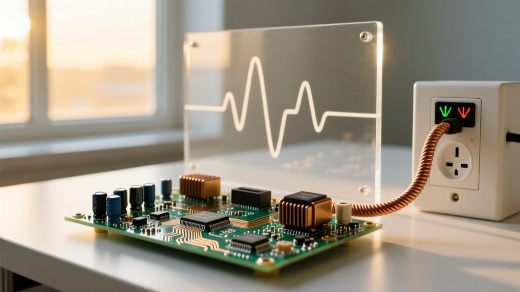
The output of a pure alternating current power source is a sine wave, mathematically represented as V(t) = V_peak * sin(2πft). According to the foundational texts at All About Circuits, this waveform is the most efficient way to transmit power over long distances because it seamlessly integrates with transformers. However, the constantly changing nature of the sine wave introduces metrics that frequently confuse beginners.
- Zero-Crossing Point: The exact moment the voltage transitions from positive to negative (or vice versa). This is a critical concept for solid-state relays (SSRs) and TRIACs, which are designed to switch loads at the zero-cross to minimize inrush current and electromagnetic interference (EMI).
- Period (T): The time it takes to complete one full 360-degree cycle. In a 60Hz system, the period is exactly 16.67 milliseconds.
- Angular Velocity (ω): Measured in radians per second, this dictates how fast the waveform oscillates and is crucial for calculating capacitive and inductive reactance.
RMS vs. Peak Voltage: The Measurement Trap
A common and potentially dangerous misconception among novice electricians is that a standard North American 120V wall outlet peaks at 120 volts. In reality, 120V is the Root Mean Square (RMS) value, which represents the equivalent DC voltage that would produce the same heating effect in a resistive load. The actual peak voltage is significantly higher.
| Nominal System Voltage | RMS Voltage | Peak Voltage (V * 1.414) | Peak-to-Peak Voltage |
|---|---|---|---|
| North American Standard | 120V | 169.7V | 339.4V |
| North American Dryer/Range | 240V | 339.4V | 678.8V |
| European/Asian Standard | 230V | 325.2V | 650.4V |
When selecting components like capacitors for AC line filtering, you must always rate them for the peak voltage, not the RMS voltage. Furthermore, when measuring distorted waveforms—such as the output of a cheap modified sine wave inverter or a Variable Frequency Drive (VFD)—a standard average-responding multimeter will yield inaccurate readings. As explained by Fluke, you must use a True-RMS multimeter to accurately measure the heating potential of non-sinusoidal AC waveforms.
Frequency Standards and Grid Architecture
The frequency of an alternating current power source defines how many complete cycles occur per second, measured in Hertz (Hz). The global grid is largely divided into two camps: 60Hz (North America, parts of South America, Japan) and 50Hz (Europe, Asia, Africa). This frequency is not arbitrary; it dictates the physical size of transformers and the synchronous speed of AC motors.
The Impact on Motor RPM
The synchronous speed of an AC induction motor is locked to the grid frequency, calculated by the formula: N_s = (120 * f) / P, where 'f' is frequency and 'P' is the number of poles. A 4-pole motor on a 60Hz source spins at 1800 RPM, while the exact same motor on a 50Hz source spins at 1500 RPM. Plugging a 50Hz-rated transformer or motor into a 60Hz alternating current power source can lead to core saturation, excessive heat, and catastrophic failure.
Single-Phase, Split-Phase, and Three-Phase Configurations
How the AC power is delivered to your workbench or job site depends on the phase configuration of the utility transformer.
Split-Phase (Residential North America)
Often mistakenly called 'two-phase,' the standard US residential supply is actually a single-phase, center-tapped system. The utility transformer secondary winding has a tap in the exact middle, which is bonded to earth ground (the Neutral). This provides 120V from either hot leg to neutral, and 240V across the two hot legs, which are 180 degrees out of phase with each other. This is why a 240V load, like a welder or water heater, does not require a neutral wire.
Three-Phase (Industrial and Commercial)
Industrial alternating current power sources utilize three separate sine waves, each offset by exactly 120 electrical degrees. This configuration delivers constant power transfer (unlike single-phase, which drops to zero 120 times a second) and allows for the use of smaller, more efficient motors and thinner conductors for the same total wattage.
Wiring Realities: Skin Effect and Impedance
When sizing wire for an alternating current power source, you must account for impedance, not just DC resistance. AC current flow creates a magnetic field that interacts with the conductor itself, leading to phenomena like the skin effect. At high frequencies, AC current prefers to travel along the outer surface (skin) of a conductor, effectively reducing the usable cross-sectional area and increasing resistance.
However, do not overestimate the skin effect at mains frequencies. At 60Hz, the skin depth of copper is approximately 8.5mm. Since a standard 14 AWG wire has a diameter of only 1.63mm, the 60Hz current fully penetrates the entire cross-section of the wire. The skin effect only becomes a critical wire-sizing factor in high-frequency applications, such as RF transmission lines or the high-frequency PWM outputs of modern motor drives, where Litz wire or specialized stranded conductors are required.
Safe Prototyping and Testing in the Lab
Interfacing directly with a mains alternating current power source is inherently lethal. When prototyping AC-to-DC power supplies or testing high-voltage AC circuits, never connect your device directly to the wall outlet. Instead, utilize an isolation transformer. This device uses magnetic coupling to transfer power without a direct galvanic connection to the earth-grounded utility neutral, drastically reducing the risk of a fatal shock if you accidentally touch a live node while grounded. Additionally, employing a Variac (variable autotransformer) allows you to slowly ramp up the AC voltage from 0V to line level, enabling you to spot wiring errors or component failures before they result in an explosive short circuit.