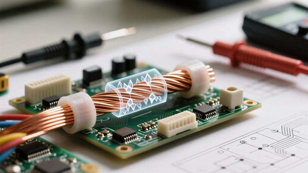

The Short Answer: Copper is a Master Conductor
If you are just starting your journey into electronics or residential wiring, you have likely asked yourself a fundamental question: is copper a copper conductor or insulator? The short answer is that copper is one of the most efficient electrical conductors on the planet. It is the global baseline against which all other conductive metals are measured. However, a complete electrical wire is actually a marriage of two opposing forces: the highly conductive copper core and the highly resistive insulating jacket that surrounds it.
Understanding the distinct roles of the copper conductor and the insulator is critical for anyone sizing wire, troubleshooting a short circuit, or designing a DIY microcontroller project. In this guide, we will break down the atomic science of why copper conducts, explore the physics of insulating materials, and provide a practical framework for selecting the right wire for your next build.
Atomic Anatomy: Why Copper Conducts Electricity So Well
To understand why copper is a conductor, we have to look at its atomic structure. According to the principles of solid-state physics detailed by resources like Georgia State University's HyperPhysics, electrical conductivity is dictated by valence electrons—the electrons in the outermost shell of an atom.
Copper (atomic number 29) has a single valence electron in its 4s orbital. This electron is very loosely bound to the nucleus. When millions of copper atoms bond together to form a wire, these outer electrons detach and form what physicists call a 'sea of free electrons.' When a voltage (electrical pressure) is applied across the wire, this sea of electrons drifts uniformly in one direction, creating an electrical current.
ETP vs. OFC: Not All Copper Wire is the Same
When you buy standard building wire or hook-up wire, you are usually buying Electrolytic Tough Pitch (ETP) copper, specifically alloy C11000. ETP copper contains a tiny amount of oxygen (about 0.02% to 0.04%), which actually helps remove impurities during the smelting process, resulting in high conductivity and excellent mechanical strength.
Conversely, Oxygen-Free Copper (OFC) is refined to remove almost all oxygen. While OFC is slightly more conductive and highly resistant to hydrogen embrittlement at high temperatures, it is expensive. For 99% of DIY electronics, automotive wiring, and residential AC circuits, standard ETP copper is the perfect choice.
Copper Conductor or Insulator? Comparing the Core Materials
When evaluating a copper conductor or insulator setup, it helps to look at the hard data. The electrical industry uses the International Annealed Copper Standard (IACS) to measure conductivity. By definition, annealed ETP copper at 20°C represents 100% IACS conductivity. Below is a comparison chart detailing how copper stacks up against other conductors and common insulating materials.
| Material | Role in Wire | Conductivity (% IACS) | Resistivity @ 20°C (nΩ·m) | Dielectric Strength (kV/mm) | Max Temp Rating |
|---|---|---|---|---|---|
| ETP Copper (C11000) | Conductor | 100% | 17.24 | N/A (Conducts) | 1083°C (Melting Point) |
| Aluminum (1350) | Conductor | 61% | 28.2 | N/A (Conducts) | 660°C (Melting Point) |
| PVC (Polyvinyl Chloride) | Insulator | 0% | >10^15 | 15 - 40 | 60°C to 105°C |
| XLPE (Cross-linked PE) | Insulator | 0% | >10^15 | 20 - 40 | 90°C to 125°C |
| PTFE (Teflon) | Insulator | 0% | >10^18 | 60 - 100 | 250°C+ |
The Insulator's Job: Dielectric Strength and Thermal Limits
If copper is the highway for electrons, the insulator is the guardrail. An insulator has tightly bound electrons that refuse to move under normal voltage conditions. However, no insulator is perfect. If the voltage gets high enough, it will literally tear electrons away from the insulating material, causing a catastrophic failure known as dielectric breakdown.
Dielectric strength is measured in kilovolts per millimeter (kV/mm). For standard low-voltage DIY projects (like a 12V Arduino circuit or a 120V AC household lamp), the dielectric strength of the insulation is rarely the limiting factor. Instead, the thermal limit of the insulator is what dictates the wire's ampacity (current-carrying capacity).
Common Wire Insulation Types for DIY and Pro Projects
According to NFPA 70 (The National Electrical Code), specifically Article 310, wire insulation is categorized by letters that denote its thermal and moisture resistance:
- THHN (Thermoplastic High Heat-resistant Nylon-coated): The most common wire for residential conduit. It features a PVC base with a slick nylon outer jacket. Rated for 90°C in dry locations.
- XHHW-2 (Cross-linked Polyethylene High Heat Water-resistant): Uses XLPE insulation. It has no nylon jacket, making it slightly thicker but vastly superior in wet locations and highly resistant to chemical degradation and sunlight.
- Silicone Rubber (e.g., AWM style 3135): Often used in DIY high-temperature applications like 3D printer heated beds or drone ESC wiring. It remains highly flexible even at extreme temperatures up to 200°C.
Practical Wiring Scenarios: When Copper and Insulators Interact
Understanding the theory of the copper conductor or insulator is only half the battle. In the real world, physical damage and environmental factors dictate how your wire performs.
The Danger of Nicking the Conductor
When stripping wire, beginners often use aggressive force with dull wire strippers, accidentally 'nicking' or cutting into the copper conductor. This does more than just weaken the wire mechanically; it reduces the effective cross-sectional area of the copper at that specific point. According to Ohm's Law, a smaller cross-section equals higher resistance. Under heavy loads, this high-resistance nick will generate localized heat, potentially melting the surrounding PVC insulation from the inside out and causing a fire hazard.
Insulation Degradation and the 'Skin Effect'
In high-frequency AC circuits (like RF antennas or high-speed data lines), electricity travels primarily on the outer surface of the copper conductor—a phenomenon known as the skin effect. If the copper is oxidized or corroded where it meets the insulator, signal integrity degrades rapidly. This is why high-frequency coaxial cables often use silver-plated copper conductors; silver resists oxidation better than bare copper and has a slightly higher conductivity, ensuring the 'skin' of the wire remains pristine.
Safety and Sizing: Matching Your Copper to the Right Jacket
When sizing wire for a project, you are technically sizing the copper conductor for the current (Amps) and the insulator for the environment (Temperature, Moisture, UV exposure). The Copper Development Association (CDA) provides extensive data on how copper's resistance increases by roughly 0.4% for every 1°C rise in temperature.
If you run a 12 AWG copper wire through a hot attic space (ambient temperature of 110°F/43°C), the copper will naturally heat up under load. If your insulation is only rated for 60°C (like older TW wire), the insulation will become brittle, crack, and expose the live conductor. Always choose an insulation rating (like 90°C THHN) that exceeds the maximum ambient and operational temperatures of your specific environment.
Pro Tip for Beginners: Never assume a wire's physical thickness equates to its copper content. Some cheap, imported extension cords use thick, low-grade PVC insulation to hide undersized, copper-clad aluminum (CCA) conductors. Always check the AWG stamp and verify the wire is solid or stranded pure copper for critical DIY and household projects.
Summary: The Perfect Electrical Partnership
So, is it a copper conductor or insulator? It is both, working in perfect opposition. The copper provides a low-resistance path for electrical energy to flow, while the insulator provides a high-resistance barrier that keeps that energy exactly where it belongs. By mastering the properties of ETP copper and understanding the thermal and dielectric limits of materials like PVC and XLPE, you will be equipped to build safer, more efficient, and longer-lasting electrical projects.





