
The Quantum Boundary: Where Conduction Meets Resistance
Every electrical circuit relies on a delicate balance between materials that allow electron flow and materials that restrict it. When evaluating conductors and insulators examples in the field, engineers cannot rely on theoretical assumptions alone; they must use precise calculations to ensure safety, efficiency, and compliance with the National Electrical Code (NEC). A conductor's primary job is to minimize energy loss, while an insulator's job is to contain the electric field and prevent catastrophic fault currents.
In this calculation tutorial, we will move beyond basic definitions. We will mathematically model real-world conductors and insulators examples, calculating voltage drop, dielectric breakdown thresholds, and insulation resistance degradation. By the end of this guide, you will have a repeatable mathematical framework for selecting and troubleshooting wiring materials in both residential and industrial environments.
Conductor Calculations: Resistivity and Voltage Drop in Action
The effectiveness of any conductor is dictated by its electrical resistivity ($\rho$), measured in ohm-meters ($\Omega \cdot m$). While silver is the most conductive element, copper and aluminum dominate the electrical industry due to their cost-to-performance ratio. To understand how these materials perform under load, we must calculate their exact resistance over a given distance.
The fundamental formula for DC resistance is:
R = $\rho$ $\times$ (L / A)
Where:
R = Resistance in Ohms ($\Omega$)
$\rho$ = Resistivity of the material ($\Omega \cdot m$)
L = Length of the conductor (meters)
A = Cross-sectional area (square meters)
Step-by-Step Example: Copper vs. Aluminum in a 100-Meter Run
Let us examine two common conductors and insulators examples by comparing a 100-meter run of 10 AWG wire (cross-sectional area = 5.26 mm², or $5.26 \times 10^{-6}$ m²) carrying a 15-amp load. According to data published by the Georgia State University HyperPhysics database, the resistivity of copper at 20°C is approximately $1.68 \times 10^{-8} \Omega \cdot m$, while aluminum is $2.82 \times 10^{-8} \Omega \cdot m$.
1. Copper Conductor Calculation:
- R = $(1.68 \times 10^{-8}) \times (100 / 5.26 \times 10^{-6})$
- R = 0.319 $\Omega$
- Voltage Drop (V = I $\times$ R) = 15A $\times$ 0.319$\Omega$ = 4.78 Volts
2. Aluminum Conductor Calculation:
- R = $(2.82 \times 10^{-8}) \times (100 / 5.26 \times 10^{-6})$
- R = 0.536 $\Omega$
- Voltage Drop (V = I $\times$ R) = 15A $\times$ 0.536$\Omega$ = 8.04 Volts
Field Takeaway: On a 120V circuit, the aluminum wire experiences a 6.7% voltage drop, which violates the NEC recommended maximum of 3% for branch circuits. To achieve the same voltage drop as copper using aluminum, you must upsize the wire gauge (e.g., from 10 AWG to 8 AWG), increasing the cross-sectional area (A) to compensate for the higher resistivity ($\rho$).
Insulator Calculations: Dielectric Strength and Thermal Limits
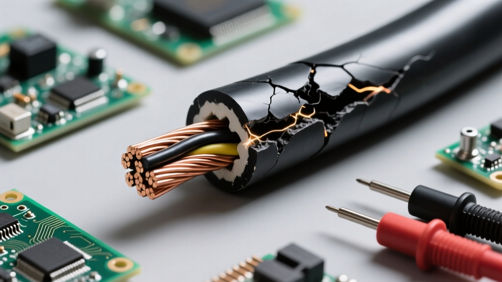
Insulators are defined by their large bandgap, which prevents valence electrons from entering the conduction band under normal conditions. However, no insulator is perfect. If the electric field exceeds the material's dielectric strength, the insulator will experience an avalanche breakdown, resulting in a short circuit or arc flash.
The breakdown voltage ($V_{bd}$) is calculated as:
$V_{bd}$ = $E_{ds}$ $\times$ t
Where:
$V_{bd}$ = Breakdown Voltage (Volts)
$E_{ds}$ = Dielectric Strength (Volts per meter, or kV/mm)
t = Thickness of the insulating material (meters, or mm)
Step-by-Step Example: PVC vs. XLPE Breakdown Voltage
When analyzing conductors and insulators examples in cable manufacturing, Polyvinyl Chloride (PVC) and Cross-Linked Polyethylene (XLPE) are the most prevalent jacketing materials. Let us calculate the theoretical breakdown voltage for a standard 0.8 mm thick insulation layer on a medium-voltage cable.
1. PVC Insulation Calculation:
- Average Dielectric Strength ($E_{ds}$) of PVC $\approx$ 40 kV/mm.
- $V_{bd}$ = 40 kV/mm $\times$ 0.8 mm = 32,000 Volts (32 kV)
2. XLPE Insulation Calculation:
- Average Dielectric Strength ($E_{ds}$) of XLPE $\approx$ 27 kV/mm.
- $V_{bd}$ = 27 kV/mm $\times$ 0.8 mm = 21,600 Volts (21.6 kV)
Field Takeaway: While PVC has a higher raw dielectric strength, XLPE is heavily preferred in high-temperature and high-stress environments. Why? Because dielectric strength degrades rapidly with heat. PVC becomes brittle and loses insulating properties above 70°C, whereas XLPE maintains structural and dielectric integrity up to 90°C (and up to 250°C under short-circuit conditions). Always cross-reference dielectric calculations with the thermal rating of the specific cable environment.
Advanced Diagnostics: Insulation Resistance and Polarization Index
In industrial settings, evaluating the health of an insulator requires more than just knowing its initial dielectric strength. Over time, moisture, dirt, and thermal cycling create conductive paths across the surface and through the bulk of the insulator. Field technicians use a Megohmmeter (Megger) to calculate the Polarization Index (PI), which indicates the moisture and contamination level of the insulation.
The formula for the Polarization Index is:
PI = $R_{10min}$ / $R_{1min}$
Where:
$R_{10min}$ = Insulation resistance measured after 10 minutes of applied DC voltage.
$R_{1min}$ = Insulation resistance measured after 1 minute.
- PI < 1.0: Dangerous. Indicates severe moisture ingress or a direct ground fault. Immediate replacement required.
- PI 1.0 - 1.5: Marginal. The insulation is degrading; schedule maintenance and cleaning.
- PI > 2.0: Excellent. The dielectric absorption current is dominating, proving the insulation is dry and healthy.
Real-World Material Selection Matrix
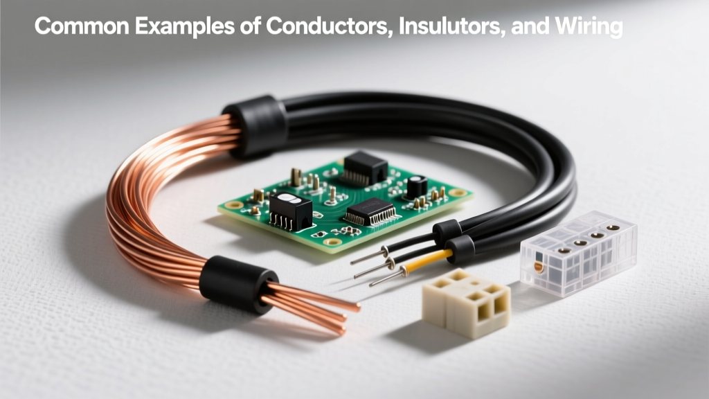
To assist in rapid field calculations and material selection, refer to the matrix below detailing standard properties for common conductors and insulators examples used in modern electrical infrastructure.
| Material Type | Role | Key Property | Standard Value | Primary Limitation |
|---|---|---|---|---|
| annealed Copper (Cu) | Conductor | Resistivity ($\rho$) | $1.68 \times 10^{-8} \Omega \cdot m$ | High density/weight; costly |
| Aluminum (Al) | Conductor | Resistivity ($\rho$) | $2.82 \times 10^{-8} \Omega \cdot m$ | Creep under pressure; oxidation |
| Polyvinyl Chloride (PVC) | Insulator | Max Operating Temp | 60°C to 70°C | Emits toxic gas when burned |
| Cross-Linked Polyethylene (XLPE) | Insulator | Max Operating Temp | 90°C | Difficult to strip; higher cost |
| Mica / Glass Fiber | Insulator | Dielectric Strength | > 100 kV/mm | Brittle; requires resin binding |
Troubleshooting Field Failures: When the Math Meets Reality
Calculations provide the baseline, but real-world failures often occur due to environmental variables not captured in standard formulas. For example, the National Institute of Standards and Technology (NIST) notes that the resistivity of copper increases by approximately 0.393% for every 1°C rise in temperature. If a conductor is routed through a hot attic space (e.g., 50°C ambient), its resistance will be significantly higher than the baseline 20°C calculation, leading to unexpected voltage drops and thermal runaway.
Similarly, insulators suffer from the "tracking" effect. If an insulator surface accumulates conductive dust and moisture, leakage currents will carve microscopic carbon paths into the material. This effectively reduces the thickness (t) in our dielectric breakdown formula, drastically lowering the $V_{bd}$ and leading to surface flashovers long before the bulk material fails.
Summary of Formulas for Field Engineers
Keep these core equations in your diagnostic toolkit when evaluating circuit integrity:
- Voltage Drop (Single Phase): $VD = \frac{2 \times K \times I \times L}{CM}$ (Where K is resistivity constant, I is current, L is length, CM is circular mils).
- Dielectric Breakdown: $V_{bd} = E_{ds} \times t$
- Leakage Current: $I_{leak} = \frac{V_{applied}}{R_{insulation}}$
By mastering the mathematics behind these conductors and insulators examples, electrical professionals can transition from simple code-followers to predictive engineers, capable of designing systems that remain safe and efficient decades into the future.