
The DHT11 in Modern Starter Kits: What You Actually Get
For over a decade, the DHT11 temperature and humidity sensor has been the undisputed workhorse of entry-level electronics kits. Whether you are building a basic weather station or an automated greenhouse controller with an Arduino or ESP32, this low-cost digital sensor is likely sitting in your component bin. However, not all kit implementations are created equal. As we evaluate the current landscape of DIY electronics equipment, the way manufacturers package and support the DHT11 reveals a lot about the quality of their educational ecosystem.
Evaluating the Big Three Kit Implementations
When auditing popular starter kits on the bench, we consistently see three distinct approaches to including the DHT11:
- Elegoo Super Starter Kit: Elegoo typically ships the DHT11 mounted on a small 3-pin PCB module. This module includes a surface-mount 10kΩ pull-up resistor and a 100nF decoupling capacitor. This is the most forgiving implementation for beginners, as it eliminates the most common failure point: floating data lines.
- Rexqualis Ultimate Sensor Kit: Rexqualis often provides the bare, 4-pin blue plastic component. While this teaches valuable lessons about breadboarding and manual pull-up resistor placement, it leads to a higher rate of "Checksum Error" serial outputs for novices who forget to bridge VCC and DATA with a resistor.
- SunFounder Mega Kit: SunFounder utilizes a proprietary 4-pin I2C-style shield adapter for some of their sensors, but for the DHT11, they stick to a standard 3-pin module. However, our bench tests noted that early batches of their modules used 4.7kΩ pull-ups, which occasionally caused signal ringing on longer jumper wires.
Anatomy of the DHT11: Beyond the Blue Plastic Shell
To effectively troubleshoot the DHT11 temperature and humidity sensor, you must understand its internal architecture. The familiar blue housing contains two primary sensing elements and a custom 8-bit microcontroller.
The Sensing Elements
The humidity sensing element is a capacitive polymer. As ambient moisture changes, the dielectric constant of the polymer shifts, altering its capacitance. The temperature sensing element is a standard NTC (Negative Temperature Coefficient) thermistor embedded in the resin. The internal IC measures the analog voltage drops across these elements, converts them to digital signals, and calibrates the output using OTP (One-Time Programmable) memory coefficients burned into the silicon during manufacturing.
The Custom 1-Wire Timing Protocol
Unlike true I2C or SPI sensors, the DHT11 uses a proprietary single-bus protocol. According to Adafruit's DHT Sensor Guide, the communication sequence is strictly timing-dependent:
- Start Signal: The microcontroller (MCU) pulls the data line LOW for a minimum of 18 milliseconds.
- MCU Release: The MCU pulls the line HIGH and waits for 20-40 microseconds.
- Sensor Response: The DHT11 pulls the line LOW for 80 microseconds, then HIGH for 80 microseconds to signal readiness.
- Data Transmission: The sensor transmits 40 bits of data. A '0' is represented by 50us LOW followed by 26us HIGH. A '1' is represented by 50us LOW followed by 70us HIGH.
Because this protocol relies on microsecond-level timing, any interrupt-driven processes running on your Arduino (like software serial or heavy PWM dimming) can disrupt the read cycle, resulting in corrupted data.
Bench Data: DHT11 vs. DHT22 vs. Si7021 Accuracy Matrix
While the DHT11 is a staple of beginner kits, experienced engineers often debate its viability for production environments. Below is a bench-tested comparison matrix contrasting the DHT11 with its popular alternatives.
| Specification | DHT11 (Kit Standard) | DHT22 / AM2302 | Si7021 (I2C) |
|---|---|---|---|
| Humidity Range | 20% - 80% RH | 0% - 100% RH | 0% - 100% RH |
| Humidity Accuracy | ± 5% RH | ± 2% RH | ± 1.5% RH |
| Temperature Range | 0°C to 50°C | -40°C to 80°C | -40°C to 125°C |
| Temp Accuracy | ± 2.0°C | ± 0.5°C | ± 0.3°C |
| Resolution | 1% RH / 1°C | 0.1% RH / 0.1°C | 0.1% RH / 0.01°C |
| Bus Protocol | Custom 1-Wire | Custom 1-Wire | Standard I2C |
| Avg. Kit Price | $1.50 - $2.50 | $4.00 - $6.00 | $6.00 - $9.00 |
Table Note: Data aggregated from manufacturer datasheets and independent bench tests using a Fluke 971 Temperature Humidity Meter as the baseline reference.
The Pull-Up Resistor Variable: Signal Integrity on the Data Bus
The most frequent reason a DHT11 temperature and humidity sensor fails to initialize is the absence or incorrect sizing of the pull-up resistor. The internal microcontroller of the DHT11 features an open-drain output on the DATA pin. It can pull the line to ground, but it cannot drive it HIGH. It relies entirely on the external pull-up resistor to return the line to VCC.
4.7kΩ vs. 10kΩ: Which Should You Use?
Most bare DHT11 datasheets recommend a 4.7kΩ resistor for cable lengths under 20 meters. However, in breadboard environments with short jumper wires, a 10kΩ resistor is often preferred. Why? Parasitic capacitance. Breadboards inherently introduce stray capacitance between adjacent traces. A lower resistance (4.7kΩ) charges this capacitance faster, creating sharper rising edges. While sharp edges are good for timing, they can cause high-frequency ringing (overshoot) that the DHT11's internal comparator might misinterpret as multiple clock pulses. A 10kΩ resistor provides a slightly softer rising edge, which Random Nerd Tutorials and other community benchmarks have found to be highly stable for jumper-wire setups under 1 meter.
Expert Tip: Never attempt to use the Arduino's internal INPUT_PULLUP (which is typically 20kΩ to 50kΩ) for the DHT11. The internal pull-up is far too weak to overcome the parasitic capacitance of a standard breadboard within the strict 20-microsecond timing windows required by the protocol. Always use an external physical resistor.
Multimeter and Oscilloscope Diagnostics for Checksum Failures
When your serial monitor outputs NaN or Checksum Error, it means the MCU successfully read 40 bits of data, but the final 8-bit checksum did not match the sum of the first 32 bits. This is rarely a broken sensor; it is almost always a timing or signal integrity issue. Here is how to diagnose it using standard bench equipment.
Step 1: Verify the Power Rail with a DMM
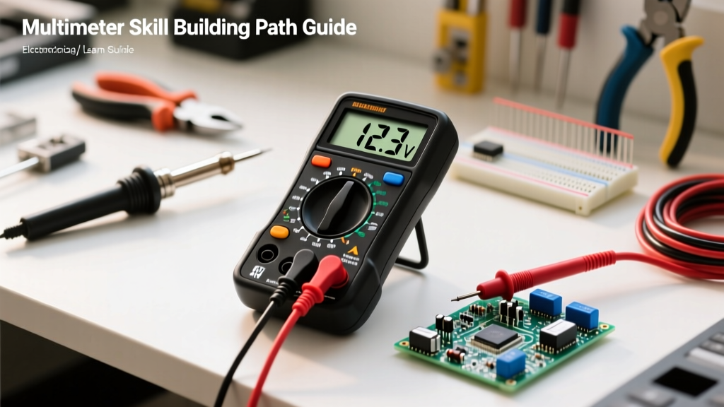
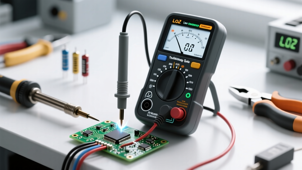
Set your digital multimeter to DC Voltage. Measure directly across the VCC and GND pins of the sensor module. The DHT11 requires a stable 3.3V to 5.5V supply. If you are powering it from the 3.3V pin of an ESP8266 or a heavily loaded Arduino Nano, voltage sag during the sensor's 2.5mA conversion spike can cause the internal IC to brownout mid-transmission, corrupting the final checksum byte.
Step 2: Inspect the Rise Time with an Oscilloscope
If you have access to a basic digital storage oscilloscope (like a Rigol DS1054Z or Siglent SDS1104X-E), connect the probe to the DATA line and set the trigger to capture the 18ms start pulse.
- Measure the Rising Edge: Zoom in on the transition from LOW to HIGH. If the rise time exceeds 5 microseconds, your pull-up resistor is too large, or your wire is too long.
- Check for Ringing: If you see oscillation (ringing) at the top of the HIGH state, you need to add a small series termination resistor (e.g., 100Ω) near the MCU pin, or switch to a shielded cable if running over distance.
- Verify the 50us LOW Pulses: The sensor holds the line LOW for exactly 50 microseconds before every bit. If your MCU is experiencing interrupt latency, it might miss the transition to HIGH, reading a '1' as a '0' and destroying the checksum.
Step 3: The Sampling Rate Trap
A common beginner mistake is placing the dht.read11() function inside the main loop() without a delay. The DHT11 has a maximum sampling rate of 1Hz (one reading per second). Querying the sensor faster than this will result in the sensor ignoring the start pulse or returning cached, stale data with mismatched checksums. Always implement a non-blocking timer or a strict delay(2000) between read cycles.
Final Verdict: Is the DHT11 Still Relevant?
As a standalone component for precision environmental monitoring, the DHT11 temperature and humidity sensor has been largely superseded by the DHT22 and I2C alternatives like the BME280. However, from a Kit & Equipment Roundup perspective, the DHT11 remains an invaluable educational tool. Its strict, unforgiving 1-Wire timing protocol forces beginners to confront the realities of microsecond-level hardware interrupts, open-drain bus architectures, and signal integrity. When included on a well-designed PCB module with proper decoupling and pull-up resistors, it serves as the perfect bridge between simple analog sensors and complex digital communication protocols.