
The Legacy Repair Dilemma: When Production Stops
When a critical piece of industrial infrastructure—like a 1998 Haas CNC mill controller or a legacy medical imaging system—fails due to a blown IC, standard distribution channels are rarely an option. If a Texas Instruments SN74LS245N octal bus transceiver or a Motorola MC68B09E microprocessor shows as "Discontinued" on DigiKey or Mouser, repair technicians must turn to the secondary market. However, as of 2026, navigating obsolete electronic components suppliers requires a rigorous troubleshooting mindset. The secondary market is heavily targeted by counterfeiters offering refurbished, re-marked, or outright fake silicon.
This guide provides a comprehensive troubleshooting framework for sourcing, vetting, and validating obsolete electronic components, ensuring your legacy repairs do not result in catastrophic field failures.
Vetting Obsolete Electronic Components Suppliers: The Risk Matrix
Not all suppliers operate with the same level of supply chain integrity. Before initiating a purchase order, troubleshoot the supplier's credibility using the matrix below. According to the Electronic Resellers Association International (ERAI), over 65% of counterfeit incidents stem from unvetted independent brokers.
| Supplier Category | Examples | Traceability Level | Pricing Premium | Counterfeit Risk |
|---|---|---|---|---|
| Authorized Obsolete Manufacturers | Rochester Electronics, Flip Electronics | 100% (Original Die/Wafer) | 300% - 800% | Near Zero |
| Franchised Legacy Distributors | Arrow, Avnet (End-of-Life divisions) | High (Direct from OEM) | 50% - 150% | Low |
| Vetted Independent Brokers | ERAI / IDEA Certified Members | Variable (Requires COC) | 20% - 400% | Moderate |
| Unvetted Marketplaces | AliExpress, eBay, Unknown Webstore | None | -50% to +100% | Extreme |
Troubleshooting Counterfeits: The Incoming Inspection Protocol
Once your components arrive from obsolete electronic components suppliers, they must undergo a strict incoming inspection before they ever touch a soldering iron. Relying on visual inspection alone is no longer sufficient, as counterfeiters in 2026 use high-precision laser etching and reclaimed packaging.
1. Microscopic Visual Inspection (10x to 40x)
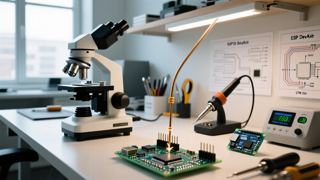
Use a stereo zoom microscope, such as the AmScope SM-4TZ (typically priced around $450), to examine the IC casing and leads.
- Font and Etching Analysis: Original 1990s and early 2000s chips often used specific ink stamps or distinct laser depths. Modern fakes frequently use cheap laser etching that looks overly crisp, lacks depth, or features inconsistent font weights on the date codes.
- Blacktopping Detection: Counterfeiters sand down the original markings of a cheaper, pin-compatible IC and apply a new layer of black epoxy ("blacktopping") to print fake part numbers. Look for a perfectly flat, matte top surface; genuine ICs usually have a slight texture or a localized indent (pin 1 marker) that feels integrated, not painted on.
2. Solvent Testing for Re-marked Chips
Apply a small amount of acetone or a specialized aerospace solvent to a cotton swab and rub the top marking vigorously for 15 seconds. If the ink smears, lifts, or the blacktop layer begins to dissolve, the part is counterfeit. Note: While some legitimate modern epoxies resist acetone, vintage 1980s-1990s epoxies may show slight, uniform degradation, whereas a fake top layer will flake or smear unevenly.
3. Lead and Solderability Analysis
"Pulled" parts—components desoldered from e-waste and sold as New Old Stock (NOS)—are a massive issue. Inspect the leads for microscopic flux residue in the crevices. Measure the lead width using high-precision digital calipers (e.g., Mitutoyo 500-196-30). Pulled and re-tinned leads are often 0.05mm to 0.10mm narrower than factory specifications due to the chemical stripping and re-dipping process.
Advanced Troubleshooting: X-Ray and Decapsulation
When sourcing high-value obsolete components—such as a $600 Xilinx XC4000 series FPGA or a custom military-grade ASIC—visual inspection is insufficient. You must troubleshoot the internal architecture.
- X-Ray Inspection ($150 - $300 per sample): X-ray imaging reveals the internal die paddle, wire bonding patterns, and die size. A common counterfeit technique involves placing a cheap, modern microcontroller die inside a legacy BGA package and wire-bonding only the power and ground pins to pass basic multimeter continuity tests. X-ray instantly exposes missing internal wire bonds.
- Chemical Decapsulation ($100 - $200 per sample): Labs use fuming nitric or sulfuric acid to etch away the epoxy casing, exposing the bare silicon die. Under high magnification, you can read the actual silicon mask ROM or die markings, which almost always reveal the true (and often inferior) origin of the chip.
Real-World Edge Cases and Failure Modes
Even when you source genuine parts from reputable obsolete electronic components suppliers, legacy components present unique physical troubleshooting challenges during the assembly phase.
Edge Case 1: The NOS Oxidation Trap
Genuine NOS parts stored for 20+ years often have severely oxidized leads. Troubleshooting Fix: Do not use abrasive sandpaper, which alters the lead geometry and compromises the mechanical fit in DIP sockets or PCB through-holes. Instead, use a specialized contact cleaner and a fiberglass scratch pen. Immediately re-tin the leads using a low-temperature solder paste (e.g., Chip Quik SMD4300AX10) before wave or selective soldering to prevent cold joints and tombstoning.
Edge Case 2: Moisture Sensitivity Level (MSL) Degradation
Vintage ICs, particularly PLCC and QFP packages, have absorbed decades of ambient moisture. If subjected to modern lead-free reflow profiles (240°C+), the trapped moisture vaporizes instantly, causing internal delamination and micro-cracking known as the "popcorn effect." Troubleshooting Fix: Per IPC/JEDEC J-STD-033 standards, baking at 125°C for 24 hours in a dedicated PCB oven is mandatory before reflow soldering any obsolete component that has been exposed to ambient air for more than a few weeks.
Edge Case 3: Electrical Parameter Drift
Semiconductors degrade over time due to electromigration and dopant diffusion, even when sitting on a shelf. A vintage 5V TTL logic chip may exhibit altered propagation delays (tpd). Troubleshooting Fix: Use a semiconductor parameter analyzer, like the Keysight B1505A, to perform curve tracing on a sample from the batch. Compare the I-V (current-voltage) curves against the original manufacturer's datasheet to ensure the internal junction characteristics match the original silicon profile.
Expert Insight: When repairing safety-critical legacy systems (e.g., aviation or medical), never rely solely on independent brokers. Always prioritize authorized obsolete manufacturers who purchase the original intellectual property and wafer designs to manufacture the chips from scratch, guaranteeing 100% silicon authenticity.
Cross-Referencing and Functional Equivalents
Sometimes, the most effective troubleshooting step is avoiding the obsolete part entirely. Utilize databases like SiliconExpert or Octopart to identify functional equivalents. For example, a discontinued Fairchild logic chip can often be replaced by a Nexperia or Toshiba drop-in replacement that shares the exact same pinout, logic thresholds, and propagation delays, but is actively in production and available from franchised distributors with full traceability.