
The DIY Benchmark: Why Pre-Assembly Component Testing Matters
Before you solder a single joint or power up a newly assembled printed circuit board (PCB), verifying your raw components is a non-negotiable step in professional electronics design and DIY fabrication. Learning how to test electronic components properly saves hours of debugging, prevents catastrophic power rail shorts, and ensures your microcontrollers and power stages operate within safe margins. Whether you are sourcing parts from a reputable distributor like Mouser or scavenging from a surplus bin, counterfeit, damaged, or out-of-spec parts can slip into your inventory.
In this comprehensive DIY guide, we will bypass generic theory and dive straight into bench-tested procedures for verifying resistors, capacitors, diodes, and transistors using a digital multimeter (DMM). We will also cover the critical distinction between in-circuit and out-of-circuit testing, a common pitfall that leads hobbyists to misdiagnose perfectly good boards.
Selecting the Right Diagnostic Tool for 2026
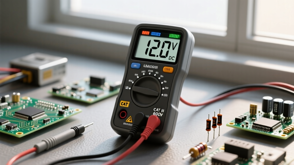
Not all multimeters are created equal when it comes to component testing. While a basic $15 meter can check continuity, precision component diagnostics require True RMS measurement, fast continuity beeping, and a reliable diode-test mode with sufficient open-circuit voltage. Below is a comparison of the top DMMs for DIY electronics testing currently dominating the market.
| Multimeter Model | Approx. Price (2026) | Best Application | Critical Testing Feature |
|---|---|---|---|
| Fluke 117 | $190 - $210 | Professional / High-Reliability DIY | AutoVolt, robust diode test, high safety rating (CAT III) |
| Brymen BM235 | $110 - $130 | Advanced DIY / Electrical Engineering | High resolution, micro-Siemens conductance, ultra-fast continuity |
| UNI-T UT61E+ | $75 - $85 | Budget / Bench Prototyping | 22,000 counts, built-in capacitance mode, PC data logging |
The Golden Rule: Out-of-Circuit vs. In-Circuit Testing
The most common mistake beginners make when learning how to test electronic components is attempting to measure them while they are still soldered to a PCB. In-circuit testing is fundamentally flawed for passive components. When you place your DMM probes across a resistor on a board, you are not just measuring that resistor; you are measuring the parallel resistance of every other trace, semiconductor junction, and capacitor connected to that same node.
Expert Insight: Always test components out-of-circuit. If you must probe in-circuit to isolate a fault, use the diode-test mode to check semiconductor junctions relative to ground, but never rely on in-circuit resistance or capacitance readings for definitive pass/fail verdicts. For deeper in-circuit diagnostics, professional repair technicians use curve tracers or specialized in-circuit ESR meters.
Step-by-Step Component Testing Procedures
1. Resistors: Checking for Drift and Tolerance
Resistors rarely fail shorted unless subjected to extreme overcurrent. They typically fail open or drift out of their specified tolerance due to thermal stress.
- Setup: Turn your DMM dial to the Ohms (Ω) setting. If your meter is not auto-ranging, select a range one decade higher than the resistor's nominal value (e.g., use the 20kΩ range for a 4.7kΩ resistor).
- Execution: Hold the probes firmly to the resistor leads. Keep your fingers off the metal tips; the human body has a resistance of roughly 100kΩ to 1MΩ, which will skew readings on high-value resistors.
- Analysis: A standard 10kΩ 5% carbon film resistor should read between 9.5kΩ and 10.5kΩ. If you measure 11.8kΩ, the resistor has experienced thermal drift and must be discarded. According to SparkFun's Multimeter Tutorial, ensuring clean probe contact is vital, as oxidation on old leads can add several ohms of parasitic resistance.
2. Capacitors: Beyond Basic Continuity (ESR and Leakage)
Testing capacitors with a standard DMM is limited. A DMM can easily identify a dead short (a catastrophic dielectric failure), but it will completely miss the most common capacitor failure mode: Equivalent Series Resistance (ESR) drift. As aluminum electrolytic capacitors age, their internal electrolyte dries out, causing ESR to spike while the actual capacitance value remains seemingly normal.
- Basic DMM Test: Set the meter to continuity or resistance. Touch the probes to the leads. You should see the resistance climb slowly to "OL" (Over Limit) as the capacitor charges. If it stays at 0Ω, the capacitor is shorted. If it immediately reads "OL" without climbing, it is open (common in ceramic caps under 10nF).
- The ESR Reality: To truly test power supply filter capacitors, you need a dedicated ESR meter, such as the Peak Atlas ESR70 (approx. $140). As detailed in All About Circuits' capacitor testing guide, an electrolytic cap measuring 1000µF but sporting an ESR of 5Ω (instead of the expected 0.05Ω) will cause massive voltage ripple and regulator instability, even though a basic capacitance meter will report it as "good."
3. Diodes and LEDs: Forward Voltage and Reverse Leakage
The diode test mode on a DMM is arguably its most useful function for semiconductor diagnostics. This mode outputs a small constant current (usually 1mA to 2mA) and measures the voltage drop across the junction.
- Forward Bias: Place the red probe on the anode and the black probe on the cathode. A standard silicon rectifier (e.g., 1N4007) will read between 0.500V and 0.700V. A Schottky diode (e.g., 1N5819) will read lower, typically 0.150V to 0.300V. An LED will display its forward voltage (e.g., 1.8V for red, 3.2V for blue) and may faintly illuminate.
- Reverse Bias: Swap the probes. The meter must read "OL". If it reads any voltage or shows continuity in reverse bias, the PN junction is compromised and the diode is leaking or shorted.
- Zener Exception: Standard DMMs output roughly 2.5V to 3V in diode mode. A 5.1V Zener diode will read "OL" in both directions on a standard meter because the test voltage is insufficient to trigger the Zener breakdown region. This is normal and does not indicate a faulty part.
4. Transistors: Junctions and Gate Oxide Integrity
Testing discrete transistors requires understanding their internal topology. We will focus on Bipolar Junction Transistors (BJTs) and N-Channel MOSFETs.
Bipolar Junction Transistors (NPN like 2N2222):
Think of an NPN BJT as two diodes sharing a common cathode (the Base). Using diode mode, place the red probe on the Base and the black probe on the Emitter, then the Collector. You should read ~0.65V for both. Swapping the probes (black on Base) should yield "OL" in both cases. If any junction reads shorted (0.00V) or open ("OL" in forward bias), the BJT is dead.
N-Channel MOSFETs (e.g., IRLZ44N):
MOSFETs are highly sensitive to Electrostatic Discharge (ESD), which punctures the microscopic silicon dioxide layer between the Gate and Source. As highlighted in Adafruit's comprehensive multimeter guide, handling MOSFETs requires ESD precautions.
- Body Diode Test: Set the DMM to diode mode. Place the red probe on the Source and the black probe on the Drain. You should read ~0.4V to 0.5V (the internal body diode). Reverse the probes; it should read "OL".
- Gate Integrity Test: Set the DMM to resistance (Ω). Measure between the Gate and Source, then Gate and Drain. Both must read strictly "OL" (infinite resistance). If you read anything less than several megaohms, the gate oxide has been punctured by ESD, and the MOSFET is a liability.
Troubleshooting Matrix: Common Failure Modes
When diagnosing a blown PCB, use this matrix to correlate your DMM readings with physical failure modes.
| Component | Visual / Circuit Symptom | DMM Out-of-Circuit Reading | Root Cause Analysis |
|---|---|---|---|
| Carbon Film Resistor | Discolored band, circuit overcurrent | Reads 20%+ higher than nominal value | Chronic thermal overstress causing material oxidation and drift. |
| Electrolytic Capacitor | Power supply ripple, switching regulator shutdown | Normal capacitance, but ESR > 1.0Ω | Internal electrolyte evaporation due to proximity to hot heatsinks. |
| Schottky Diode | Rectifier stage failure, excessive heat | Reads 0.3V in forward, but 0.8V in reverse | Junction thermal runaway causing severe reverse leakage current. |
| Logic-Level MOSFET | Load stuck permanently ON or OFF | Gate-to-Source reads 150Ω (instead of OL) | Gate oxide puncture from ungrounded soldering iron or ESD event. |
Final Thoughts on Bench Best Practices
Mastering how to test electronic components is about more than just reading a display; it is about understanding the physics of the component and the limitations of your test equipment. Always discharge high-capacitance capacitors safely with a high-wattage bleeder resistor before testing, keep your DMM probes clean with isopropyl alcohol to prevent contact resistance errors, and invest in a dedicated ESR meter if your DIY projects frequently involve repairing or building analog power supplies. By integrating these rigorous testing protocols into your workflow, you will drastically reduce your debugging time and build significantly more reliable electronics.