
The Multimeter Learning Curve: From Novice to Diagnostician
Learning how to work with a multimeter is not a single event; it is a progressive journey. Many beginners buy a digital multimeter (DMM), measure a AA battery, and falsely assume they have mastered the tool. True proficiency requires understanding the internal architecture of the meter, the physics of the circuit under test, and the severe safety implications of incorrect probe placement. This guide provides a structured, four-phase skill-building path designed to take you from basic continuity checks to advanced industrial diagnostics.
Phase 1: Core Familiarization and Safety Protocols
Before you ever touch a live circuit, you must understand the safety boundaries of your equipment. Multimeters are categorized by Overvoltage Installation Categories (CAT ratings), which define their ability to withstand transient voltage spikes.
Understanding CAT Ratings and Probe Placement
A CAT II 600V meter is suitable for household appliances and standard outlets. However, if you are measuring the main service panel or outdoor utility lines, you need a CAT III or CAT IV rated meter. According to Fluke's safety guidelines, a CAT III 1000V meter has a significantly higher internal impedance and arc-flash resistance than a CAT II 1000V meter, despite the identical voltage rating. Always verify your test leads also carry the appropriate CAT rating; the meter and leads are a matched safety system.
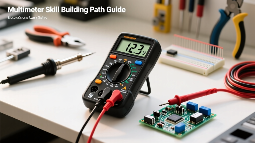
Your DMM typically features three or four input jacks:
- COM (Common): The ground reference. Your black lead always stays here.
- V/Ω/Diode: Used for voltage, resistance, and continuity. Internally, this port has a high impedance (usually 10 Megohms) to prevent the meter from loading the circuit.
- mA/µA: For low current measurements. This port is protected by a delicate, fast-acting internal fuse.
- 10A (Unfused or High-Current): For measuring up to 10 Amps. This port bypasses the delicate internal fuses and uses a heavy-duty shunt resistor.
Phase 2: Mastering the Core Trinity (Voltage, Resistance, Continuity)
The foundation of electrical troubleshooting rests on three primary measurements. As noted in the SparkFun Multimeter Tutorial, understanding whether to connect your meter in parallel or in series is the most critical conceptual hurdle for beginners.
Measurement Modes and Common Pitfalls
| Measurement | Meter Connection | Circuit State | Common Pitfall & Failure Mode |
|---|---|---|---|
| Voltage (V) | Parallel | Energized (Live) | Leaving leads in the current jacks, causing a dead short across the voltage source and blowing the meter's main fuse. |
| Resistance (Ω) | Parallel | De-energized (Dead) | Measuring resistance on a live circuit, which feeds external voltage back into the meter's sensitive ohmmeter circuitry, destroying the internal ADC. |
| Continuity | Parallel | De-energized (Dead) | Failing to isolate components. Parallel circuit paths will yield false continuity readings, leading to misdiagnosis of short circuits. |
The Continuity Trap and the Diode Test
Continuity mode sends a tiny current through the probes and beeps if the resistance is below a certain threshold (usually 15-40 ohms). However, relying solely on the beep is a novice mistake. Instead, transition to using the Resistance (Ω) mode to see the exact value. A connection with 5 ohms of resistance might pass a continuity test but will cause a massive, unacceptable voltage drop in a high-current 12V automotive circuit.
Furthermore, master the Diode Test mode. This mode outputs a higher open-circuit voltage (typically 2-3V) than continuity mode. It is invaluable for testing semiconductor junctions. A healthy silicon diode will show a forward voltage drop between 0.5V and 0.7V, and an 'OL' (Open Loop) in reverse bias. You can also use this mode to verify the health of LED lighting and transistor base-emitter junctions without removing them from the board.
Phase 3: Intermediate Diagnostics (Current and Voltage Drop)
Once you are comfortable with voltage and resistance, you must tackle the most dangerous and most revealing measurements: current and voltage drop.
The Blown Fuse Scenario: Measuring Current Safely
To measure current, the multimeter must become part of the circuit. You must break the circuit and wire the meter in series. Internally, the meter uses a precision shunt resistor and measures the voltage drop across it to calculate current via Ohm's Law. Because the shunt resistor has near-zero resistance, placing your meter in current mode across a voltage source (in parallel) creates a dead short. This will instantly vaporize the internal traces if the meter lacks proper High Rupture Capacity (HRC) fuses. Always double-check your probe placement before energizing a circuit for current measurement.
The Electrician's Secret: Voltage Drop Testing
Expert Diagnostic Rule: Never measure resistance to find a bad connection in a high-current circuit. Measure the voltage drop while the circuit is under load.
According to All About Circuits, voltage drop testing is the definitive way to locate hidden resistance. If a 120V AC motor is underperforming, measuring the outlet might show 120V. But if you measure from the hot side of the outlet to the hot terminal of the motor while it is running, and you read 15V, you have found 15 volts of 'lost' energy. That 15V drop indicates severe corrosion, a loose termination, or undersized wiring that a standard continuity test would completely miss.
Phase 4: Advanced Techniques (True RMS and Ghost Voltages)
The final phase of your skill-building path involves dealing with non-ideal, real-world electrical noise and non-linear loads.
True RMS vs. Average Responding
Cheap multimeters are 'average responding.' They assume the AC waveform is a perfect sine wave, measure the average, and multiply it by a constant (1.11) to display the RMS value. However, modern electronics, variable frequency drives (VFDs), and LED drivers create heavily distorted, non-sinusoidal waveforms. An average-responding meter can be off by up to 40% on these circuits. Upgrading to a True RMS multimeter (like the Fluke 115 or Klein MM700) ensures the meter calculates the actual heating effect of the complex waveform, giving you accurate readings regardless of harmonic distortion.
Eliminating Ghost Voltages with LoZ
When troubleshooting industrial control panels or long residential cable runs, you will often encounter 'ghost voltages'—phantom readings of 40V to 90V on disconnected wires caused by capacitive coupling from adjacent live wires. Advanced meters feature a LoZ (Low Impedance) mode. By intentionally lowering the meter's input impedance from 10 Megohms down to roughly 3 kilohms, the meter bleeds off the capacitive phantom voltage, dropping the reading to zero and confirming the wire is truly dead. This prevents technicians from wasting hours chasing non-existent voltage faults.
Recommended Gear for Your Progression
Your tool should evolve as your skills do. Here is a practical hardware progression path:
| Skill Level | Recommended Model | Key Features & Justification | Approx. Price |
|---|---|---|---|
| Beginner (Phase 1-2) | Klein Tools MM400 | Auto-ranging, CAT III 600V, basic continuity. Perfect for learning the interface without breaking the bank. | $45 - $55 |
| Intermediate (Phase 3) | Fluke 115 | True RMS, robust HRC fuses, MIN/MAX recording for capturing inrush currents. | $170 - $200 |
| Advanced (Phase 4) | Fluke 87V | LoZ mode, high-resolution mode, temperature, frequency, and duty cycle. The industry standard for master electricians. | $450 - $500 |
Conclusion
Mastering how to work with a multimeter is about building a mental framework of circuit behavior. By progressing from basic safety and parallel voltage measurements to series current diagnostics and advanced True RMS analysis, you transform from a simple meter-reader into a true electrical diagnostician. Always respect the energy you are measuring, verify your probe placements twice, and let the data guide your troubleshooting logic.