
The Shift from Measuring to Diagnosing
Learning how to operate a multimeter is often reduced to memorizing dial positions: voltage goes here, resistance goes there. But for electricians, electronics technicians, and advanced DIYers, a multimeter is not just a measuring device; it is a diagnostic engine. Measuring tells you what a circuit is doing right now. Troubleshooting tells you why it is doing it, and more importantly, how to fix it.
In this comprehensive troubleshooting guide, we will bypass the basic "how to measure a battery" tutorials and dive straight into advanced diagnostic techniques. We will cover voltage drop testing, eliminating ghost voltages, interpreting dead-circuit resistance, and avoiding the catastrophic operator errors that destroy meters and trip main breakers.
The Anatomy of a Diagnostic Multimeter
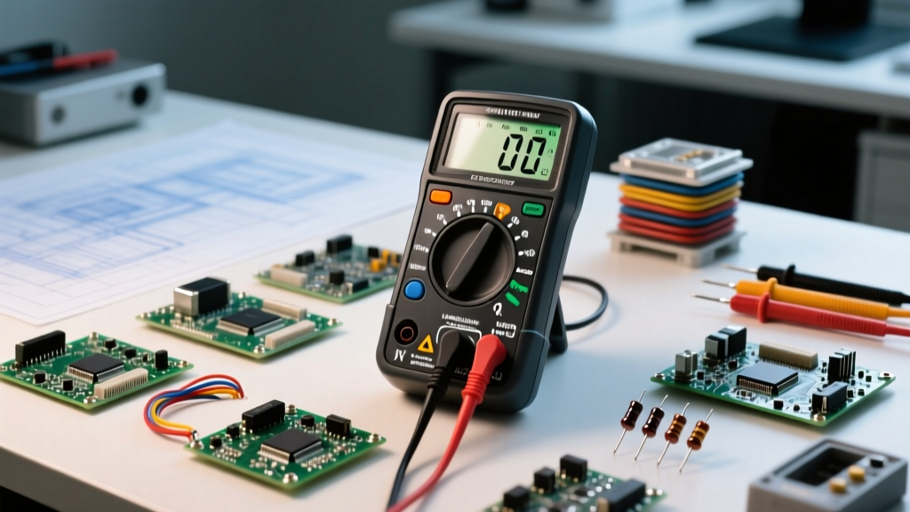
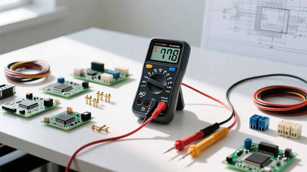
Before troubleshooting, you must understand the internal architecture of your tool. Let us use the industry-standard Fluke 117 True RMS Multimeter and the popular Klein Tools MM400 as our reference points. A diagnostic meter relies on four critical input jacks:
- COM (Common): The ground reference for all measurements. The black probe always lives here.
- VΩ (Volts/Ohms): Protected by an internal high-energy fuse. Used for voltage, resistance, continuity, and diode testing.
- mA/µA (Milliamps/Microamps): Protected by a secondary, fast-acting fuse. Used for low-current diagnostic loops (e.g., 4-20mA industrial sensors).
- 10A (Amps): Often unfused or protected only by a high-rupture-capacity fuse. Used for high-draw loads like automotive starters or HVAC compressors.
Critical Safety Warning: Never place your red probe in the 10A or mA jack and attempt to measure voltage across a power source. You are effectively placing a dead short across the line. This will instantly blow the internal fuse, destroy the meter's PCB traces, and potentially cause an arc flash. Always verify your probe placement before touching a live circuit.
Safety First: CAT Ratings and Probe Inspection
When troubleshooting live industrial or residential panels, your multimeter's CAT (Measurement Category) rating is your primary defense against transient voltage spikes. According to Fluke's guide on understanding multimeter CAT ratings, a CAT III 600V meter is designed to withstand the impedance and transient spikes found in fixed building wiring, while a CAT IV 600V meter is required for the service entrance and outdoor utility connections.
Before every troubleshooting session, perform a physical inspection of your test leads. Look for cracked insulation, exposed wire near the probe tip, or loose banana plug connections. A compromised test lead can turn a routine 120V receptacle test into a severe shock hazard.
Step-by-Step: How to Operate a Multimeter for Continuity
Continuity testing is the bedrock of dead-circuit troubleshooting. It answers a simple binary question: Is there a continuous electrical path between point A and point B?
- De-energize the circuit. Never test continuity on a live circuit. The presence of voltage will feed back into the meter's ohmmeter circuit, yielding false readings and potentially damaging the meter.
- Set the dial to Continuity (the soundwave icon).
- Touch the probes together. You should hear an immediate beep, and the display should read near 0.0 Ω. This confirms your leads are intact.
- Test the component. Place probes across a fuse, a switch, or a length of wire.
Pro Tip: Do not rely solely on the audible beep. The beep threshold on most meters is around 30 to 50 ohms. If you are troubleshooting a precision sensor or a relay coil, a reading of 45 ohms might beep, indicating continuity, but it could actually represent a degraded, high-resistance connection that will fail under load. Always read the digital ohm value for critical components.
Troubleshooting Live Circuits: Voltage Drop Testing
Most beginners troubleshoot voltage by measuring from the power source to ground, and then from the load to ground. This is an inefficient method that often masks high-resistance faults. The professional method is Voltage Drop Testing.
As explained in Fluke's technical breakdown of voltage drop testing, voltage drop is the measurement of electrical pressure lost as current pushes through a resistance. In a healthy circuit, switches, connectors, and wires should have virtually zero resistance, meaning they should drop zero voltage.
How to Perform a Voltage Drop Test
- Set your multimeter to DC or AC Voltage, matching the circuit type.
- Leave the circuit energized and under load (e.g., the motor must be trying to run, or the headlight must be switched on).
- Place your red probe on the power side of the component (e.g., the battery side of a switch) and your black probe on the load side of the exact same component.
- The Diagnosis: A healthy switch or wire will read 0.00V to 0.2V. If your meter reads 4.5V across a 12V automotive switch, that switch has internal carbon buildup and is stealing voltage from the load.
Interpreting the Readings: A Fault Diagnosis Matrix
Use this matrix to rapidly isolate faults based on your multimeter's behavior during live and dead testing scenarios.
| Symptom | Multimeter Setting | Expected Reading | Actual Reading | Probable Fault |
|---|---|---|---|---|
| Motor won't start | DC Voltage (Across load) | Source Voltage (e.g., 24V) | 0V | Open circuit upstream (blown fuse, broken wire, tripped breaker) |
| Dim lights / slow motor | DC Voltage (Across switch) | 0.00V - 0.2V | 4.5V | High resistance in switch contacts or corroded terminal |
| Breaker trips instantly | Resistance (Power OFF) | OL (Over Limit) | 0.5 Ω | Dead short to ground or neutral-to-hot contact |
| Phantom voltage on wire | AC Voltage (LoZ Mode) | 120V | 0.0V | Capacitive coupling (Ghost voltage from adjacent live wires) |
Common Multimeter Operator Errors and How to Fix Them
Even experienced technicians fall victim to specific multimeter quirks. Here is how to troubleshoot your troubleshooting tool.
The "Ghost Voltage" Phenomenon
When pulling a new cable through a conduit next to an active 120V AC line, you might measure 40V to 80V on the disconnected wire using your multimeter's standard AC voltage setting. This is capacitive coupling. Digital multimeters have an extremely high internal input impedance (usually 10 Megohms), making them sensitive enough to read the electromagnetic "ghost" voltage induced by the neighboring wire.
The Fix: Switch your meter to LoZ (Low Impedance) mode if available (standard on the Fluke 117). LoZ places a low-impedance load on the circuit, bleeding off the phantom capacitive energy and dropping the reading to a true 0.0V. If your meter lacks LoZ, plug a small incandescent test light or a solenoid voltage tester (Wiggy) between the wire and ground to dissipate the ghost voltage.
The Blown Internal Fuse Mystery
If your meter reads "OL" or zero when measuring current in the mA jack, but works perfectly for voltage, you have likely blown the internal mA fuse. This happens when a technician forgets to move the red probe from the mA jack back to the VΩ jack and subsequently measures voltage across a battery. Always carry spare ceramic HRC fuses specific to your meter's exact amperage and voltage rating. Never bypass a blown fuse with a piece of wire or foil.
Pro Tips for Intermittent Faults
Intermittent faults—where a machine fails only when it vibrates or reaches a certain temperature—are the bane of electrical diagnostics. You cannot stare at a multimeter screen for three hours waiting for a glitch.
Utilize your meter's MIN/MAX recording mode. When activated, the meter samples the circuit multiple times per second and stores the highest and lowest readings in its memory. Connect the probes across the suspected power supply, hit MIN/MAX, and let the machine run through its failure cycle. When the fault occurs, check the MIN reading. If the 24V control circuit dipped to 14V for a fraction of a second, you have just caught an intermittent voltage drop caused by a failing power supply or a loose crimp connection.
For comprehensive safety standards regarding live electrical work, always consult and adhere to OSHA's electrical safety guidelines and NFPA 70E protocols. Mastering how to operate a multimeter is as much about protecting yourself as it is about protecting the circuits you diagnose.