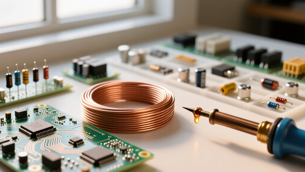

The Atomic Conductor Science Definition in Electrical Engineering
Before you can accurately size a wire or calculate voltage drop, you must understand the fundamental physics governing electron flow. The strict conductor science definition in solid-state physics describes a material in which the valence band and conduction band overlap. Unlike insulators or semiconductors, conductors possess a 'sea of free electrons' that are not bound to any specific atom. When an electromotive force (voltage) is applied, these delocalized electrons drift through the atomic lattice, creating an electrical current.
However, this atomic lattice is not perfectly empty. As electrons move, they collide with vibrating atoms (phonons) and impurities in the metal. These collisions create opposition to the flow of current, a property we define as electrical resistance. For DIYers, electricians, and engineers, bridging the gap between this quantum mechanical definition and practical circuit mathematics is the key to preventing overheated wires, excessive voltage drop, and catastrophic electrical fires.
Translating Physics into Wire Sizing Math
To move from the theoretical conductor science definition to actionable wire sizing, we rely on the macroscopic property of resistivity (denoted by the Greek letter rho, $\rho$). Resistivity is an intrinsic property of a material that quantifies how strongly it opposes the flow of electric current. According to HyperPhysics at Georgia State University, the resistance ($R$) of a uniform conductor is directly proportional to its length ($L$) and inversely proportional to its cross-sectional area ($A$).
The foundational physics formula is:
$R = \rho \times (L / A)$
- $R$ = Resistance in Ohms ($\Omega$)
- $\rho$ = Resistivity of the material (e.g., $\Omega\cdot\text{m}$)
- $L$ = Length of the conductor
- $A$ = Cross-sectional area
Adapting the Formula for the American Wire Gauge (AWG) System
In North America, electrical professionals rarely use square meters for wire area. Instead, the National Electrical Code (NEC) and wire manufacturers utilize Circular Mils (cmil). A circular mil is the area of a circle with a diameter of one mil (one-thousandth of an inch). Furthermore, we replace the resistivity constant ($\rho$) with a standardized K-factor, which represents the resistance of a wire one foot long with a cross-sectional area of one circular mil.
The practical calculation formula becomes:
$R = \frac{K \times L}{cmil}$
For DC circuits or precise 20°C laboratory conditions, the K-factor for annealed copper is approximately 10.37. However, as noted by the Copper Development Association, real-world AC circuits operate at higher temperatures (typically 75°C for THHN insulation under load). Therefore, for practical AC voltage drop calculations, we use an adjusted K-factor of 12.9 for copper and 21.2 for aluminum.
Step-by-Step Calculation: Sizing a 240V EV Charger Circuit
Let us apply the conductor science definition and our adapted K-factor formula to a real-world scenario. You are installing a Level 2 Electric Vehicle (EV) charger that requires a 50-Amp continuous load. The panel is located 80 feet away from the charger. The NEC recommends keeping voltage drop under 3% for optimal efficiency and equipment longevity.
Step 1: Determine Maximum Allowable Voltage Drop
For a 240V system, a 3% drop is calculated as:
$240\text{V} \times 0.03 = \mathbf{7.2\text{V maximum drop}}$
Step 2: Rearrange the Formula to Solve for Circular Mils (cmil)
Because voltage drop ($V_d$) in a single-phase circuit must account for the distance out and back, the total wire length is $2 \times L$. The voltage drop formula is $V_d = \frac{2 \times K \times I \times L}{cmil}$. Rearranging to solve for the required wire size:
$cmil = \frac{2 \times K \times I \times L}{V_d}$
Step 3: Plug in the Constants
- $K$ = 12.9 (Copper at 75°C operating temp)
- $I$ = 50 Amps
- $L$ = 80 feet (one-way distance)
- $V_d$ = 7.2 Volts
$cmil = \frac{2 \times 12.9 \times 50 \times 80}{7.2}$
$cmil = \frac{103,200}{7.2} = \mathbf{14,333\text{ cmil}}$
Step 4: Select the Proper AWG Wire
Consulting a standard wire gauge chart, a 10 AWG copper wire has an area of 10,380 cmil (too small). An 8 AWG copper wire has an area of 16,510 cmil. Because 16,510 is greater than our calculated requirement of 14,333, 8 AWG THHN copper is the scientifically and practically correct choice to maintain a safe voltage drop while adhering to thermal limits defined by NFPA 70 (NEC).
Factoring in the Temperature Coefficient of Resistance
A critical component of the conductor science definition is that resistivity is not static; it is highly temperature-dependent. As a wire carries current, it generates heat ($I^2R$ losses). This heat causes the atomic lattice to vibrate more violently, increasing the frequency of electron collisions and thereby raising the resistance.
To calculate the exact resistance of a conductor at its operating temperature, we use the temperature coefficient formula:
$R_T = R_0 [1 + \alpha(T - T_0)]$
- $R_T$ = Resistance at operating temperature
- $R_0$ = Resistance at baseline temperature (usually 20°C)
- $\alpha$ = Temperature coefficient of resistance (for copper, $\alpha \approx 0.00393 / ^\circ\text{C}$)
- $T$ = Operating temperature (e.g., 75°C)
- $T_0$ = Baseline temperature (20°C)
Calculation Example: If a copper wire has a baseline resistance of 1.0 $\Omega$ at 20°C, its resistance at a full-load operating temperature of 75°C will be:
$R_{75} = 1.0 \times [1 + 0.00393(75 - 20)]$
$R_{75} = 1.0 \times [1 + 0.00393(55)]$
$R_{75} = 1.0 \times [1 + 0.21615] = \mathbf{1.216\Omega}$
This reveals a massive 21.6% increase in resistance simply due to operational heating. This is precisely why using the laboratory K-factor (10.37) for building wire calculations is dangerous; it underestimates resistance and voltage drop by over 20% under real-world load conditions.
Reference Table: Conductor Material Constants
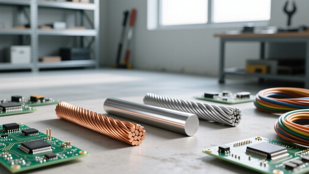
When designing circuits or substituting materials (e.g., choosing aluminum feeders over copper for a 200A subpanel to save money), you must adjust your calculations based on the specific atomic properties of the metal.
| Material | Resistivity at 20°C ($\Omega\cdot\text{m} \times 10^{-8}$) | K-Factor (AC/75°C) | Temp Coefficient ($\alpha$) | Relative Conductivity (% IACS) |
|---|---|---|---|---|
| Silver | 1.59 | ~11.5 | 0.00380 | 105% |
| Copper (Annealed) | 1.72 | 12.9 | 0.00393 | 100% |
| Gold | 2.44 | ~16.5 | 0.00340 | 70% |
| Aluminum (1350) | 2.82 | 21.2 | 0.00403 | 61% |
Expert Insight: Notice that while Aluminum has a significantly higher resistivity (requiring a wire size roughly two AWG steps larger than copper for the same ampacity), its temperature coefficient ($\alpha$) is nearly identical. However, aluminum's tendency to oxidize and undergo thermal creep at termination points requires strict adherence to torque specifications and the use of antioxidant pastes, bridging the gap between material science and field installation practices.
Summary: Bridging Theory and Practice
Understanding the conductor science definition is not merely an academic exercise. By recognizing that conductors are materials with overlapping energy bands that suffer from thermal and physical electron scattering, you can make highly accurate, safe, and cost-effective wiring decisions. Whether you are calculating the circular mils required for a solar array inverter or adjusting for the temperature coefficient in a high-heat attic environment, relying on the fundamental physics formulas ensures your DIY and professional electrical projects perform flawlessly under load.