
The Core Direct Current and Alternating Current Definition
When designing circuits, selecting wire gauges, or troubleshooting a microcontroller power supply, understanding the fundamental physics of electricity is non-negotiable. At the heart of electrical engineering lies the direct current and alternating current definition. While often simplified in basic textbooks, the real-world behavior of these two current types dictates everything from wire sizing to safety protocols and component selection.
Quick Reference Definition:
Direct Current (DC): The unidirectional flow of electric charge. Voltage maintains a constant polarity over time, resulting in a steady electron drift from the negative to the positive terminal.
Alternating Current (AC): The periodic reversal of electric charge flow. Voltage and current alternate direction, typically following a sinusoidal waveform at a specific frequency (e.g., 50Hz or 60Hz).
In practical DIY electronics, you are almost always bridging these two worlds. The grid delivers AC to your workbench, but your Arduino, ESP32, or Raspberry Pi requires pristine DC. Understanding the exact physical differences between the two is the first step in mastering power supply design and wire sizing.
Waveform Anatomy & Mathematical Representation
To move beyond the basic direct current and alternating current definition, we must look at the mathematical models that govern them. This is critical when sizing capacitors for filtering or selecting diodes for rectification.
Direct Current (DC) Math
Ideal DC is represented as a flat line: V(t) = V_dc. However, in real-world DIY power supplies, DC is rarely perfect. It contains ripple voltage, which is the residual AC variation left over after rectification. When sizing wire for a DC circuit, you calculate the continuous thermal load based on the RMS (Root Mean Square) current, which for pure DC is simply the average current.
Alternating Current (AC) Math
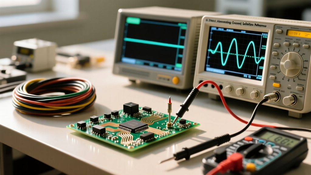
AC voltage is defined by the equation: v(t) = V_peak * sin(2πft + φ).
Here, f is the frequency and φ is the phase angle. The most critical concept for DIYers to grasp is RMS (Root Mean Square) voltage. When we say a US wall outlet is 120V AC, that is the RMS value. The actual peak voltage hitting your components is approximately 170V (120V * √2). If you are selecting a smoothing capacitor for a bridge rectifier, it must have a voltage rating safely above 170V, not 120V, to avoid catastrophic dielectric failure.
Quick-Reference Comparison Matrix
Use the following matrix as a cheat sheet when transitioning between AC mains design and DC logic-level circuitry.
| Parameter | Direct Current (DC) | Alternating Current (AC) |
|---|---|---|
| Charge Flow | Unidirectional (Constant polarity) | Bidirectional (Periodic reversal) |
| Frequency | 0 Hz (Zero crossings) | 50 Hz or 60 Hz (Mains), up to GHz (RF) |
| Power Factor | Always 1.0 (Unity) | Varies between 0 and 1.0 (Reactive loads) |
| Wire Sizing Factor | Based on continuous thermal ampacity | Must account for Skin Effect at high frequencies |
| Generation Source | Batteries, Solar Cells, DC Generators, Rectifiers | Alternators, Grid Inverters, Oscillators |
| Typical DIY Voltage | 3.3V, 5V, 12V, 24V, 48V | 120V, 240V (Mains), 12V-24V (Low voltage AC) |
| Hazard Profile | Causes continuous muscle contraction; higher let-go threshold | Causes muscle tetany (fibrillation); lower let-go threshold |
Transmission Losses & The Skin Effect
Why did AC win the 'War of the Currents' in the late 19th century, and why is High-Voltage DC (HVDC) making a comeback today? The answer lies in transmission physics.
AC allows the use of transformers to step up voltage for long-distance transmission, drastically reducing I²R (heat) losses. However, AC suffers from the Skin Effect. As AC frequency increases, the alternating magnetic field induces eddy currents that push the electron flow toward the outer 'skin' of the conductor.
- At 60 Hz (Mains AC): The skin depth in copper is roughly 8.5mm. Standard household wire (e.g., 12 AWG, 2.05mm diameter) is fully utilized.
- At 1 MHz (RF/High-Frequency AC): The skin depth shrinks to 0.065mm. The center of a solid copper wire becomes useless, which is why high-frequency AC applications require specialized Litz wire or hollow copper tubing.
DC, having a frequency of 0 Hz, utilizes the entire cross-sectional area of the wire evenly. This is why HVDC is now preferred for ultra-long-distance submarine cables—there is no skin effect, no reactive power loss, and no capacitive charging current.
Practical DIY & Microcontroller Implications
For the electronics hobbyist, the transition from the direct current and alternating current definition to actual circuit building requires mastering rectification and filtering.
The Rectification Stage
Converting AC to DC requires a bridge rectifier. A common DIY component is the KBPC5010, a 50-Amp, 1000V bridge. When AC passes through this bridge, it flips the negative half-cycles into positive ones, creating 'pulsating DC.' This is not yet safe for a microcontroller.
The Filtering Stage
To smooth pulsating DC into a flat line, we use electrolytic capacitors. The required capacitance can be calculated using the quick-reference formula:
C = I / (2 * f * ΔV)
Where I is the load current, f is the AC frequency (60Hz), and ΔV is your acceptable ripple voltage. If your ESP32 draws 0.5A and you can tolerate 0.1V of ripple on a 60Hz supply, you need a minimum of 0.5 / (2 * 60 * 0.1) = 41,666 µF. In practice, DIYers will parallel multiple 10,000µF capacitors to achieve this, highlighting the physical bulk required to tame AC ripple in high-current DC supplies.
Safety Thresholds & Physiological Impact
According to the IEC 60479-1 standard, the human body reacts very differently to AC and DC shocks, which must inform your workbench safety protocols.
Because AC crosses zero volts 120 times a second (in a 60Hz system), it triggers rapid, repetitive muscle contractions. This leads to tetany, where the muscles clench and the victim cannot let go of the live conductor. The 'let-go' threshold for AC is dangerously low, typically around 10mA to 20mA.
DC, conversely, causes a single, massive muscle contraction that often throws the victim away from the source. The let-go threshold for DC is much higher, around 50mA to 80mA. However, DC arcs are notoriously difficult to extinguish because there is no zero-crossing point to naturally break the plasma bridge, making DC disconnect switches and fuses fundamentally different—and often more expensive—than their AC counterparts.
Authoritative Standards & Further Reading
To deepen your understanding of electrical fundamentals beyond this quick reference, consult the following authoritative resources:
- Georgia State University HyperPhysics: An exceptional resource for the mathematical derivations of AC/DC waveforms and RMS calculations. Explore their Electric Current and AC/DC modules.
- All About Circuits: For practical applications of AC measurements, phase angles, and reactance, review the Alternating Current (AC) Textbook Volume II.
- National Institute of Standards and Technology (NIST): For the fundamental constants of electron charge and drift velocity physics that underpin the direct current definition.
Whether you are calculating voltage drop for a 12V DC solar array or wiring a 240V AC split-phase workshop outlet, keeping the distinct physical properties of these two current types at the forefront of your design process will ensure safety, efficiency, and project longevity.