
Understanding AC Electro-Magnetic Field Dynamics
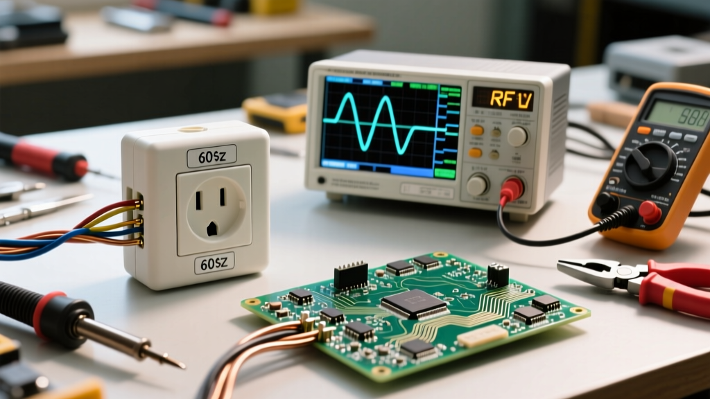
When designing electrical systems, the transition from Direct Current (DC) to Alternating Current (AC) introduces complex physical phenomena that fundamentally alter how conductors behave. Unlike DC, which distributes current evenly across a wire's cross-section, AC current generates continuously expanding and collapsing magnetic fields. These AC electro-magnetic fields interact with the conductor itself, adjacent wires, and surrounding metallic infrastructure, resulting in increased effective resistance, heat generation, and electromagnetic interference (EMI).
For electrical engineers and advanced DIYers, ignoring these AC electro-dynamic effects can lead to undersized conductors, excessive voltage drop, and catastrophic thermal failures. This guide explores the physics of AC electromagnetic fields, how they dictate wire sizing, and the shielding frameworks required to maintain signal integrity and safety.
The Skin Effect in Copper and Aluminum
The skin effect is the tendency of alternating current to concentrate near the outer surface of a conductor, effectively reducing the usable cross-sectional area and increasing AC resistance. The depth at which current density falls to 37% of its surface value is known as the skin depth ($\delta$).
At a standard power frequency of 60 Hz, the skin depth in copper is approximately 8.5 mm. Because most standard building wires (up to 500 kcmil) have a radius smaller than 8.5 mm, the skin effect at 60 Hz is relatively negligible for residential wiring. However, in high-frequency applications (such as 400 Hz aerospace power systems or variable frequency drives operating at high PWM switching frequencies), the skin depth shrinks dramatically. At 400 Hz, the skin depth in copper drops to roughly 3.3 mm. Consequently, a 4/0 AWG wire (radius ~5.8 mm) will have a significant 'dead zone' in its center, forcing engineers to use multiple smaller stranded conductors or specialized Litz wire to maintain ampacity.
Proximity Effect and Hysteresis Losses
While the skin effect is an internal phenomenon, the proximity effect occurs when the AC electro-magnetic field of one conductor induces eddy currents in an adjacent conductor. When AC phase conductors are routed tightly together, their overlapping magnetic fields force the current to crowd toward the facing surfaces of the wires. This localized crowding increases the AC resistance beyond what the skin effect alone would cause. In high-current busbar installations, proximity effect losses can account for a 10% to 20% increase in total thermal output, necessitating physical spacing or forced air cooling.
NEC Article 300.20: Induced Currents in Ferrous Metals
One of the most critical safety considerations regarding AC electro-magnetic fields is their interaction with ferrous (magnetic) metals, such as steel conduit. According to NFPA 70: National Electrical Code (NEC) Article 300.20, if a single AC phase conductor carrying high current is routed through a steel conduit alone, the alternating magnetic field will induce massive eddy currents in the steel. The conduit essentially acts as the short-circuited secondary winding of a transformer.
This induced current causes the steel conduit to heat up rapidly, potentially melting wire insulation and starting a fire. To cancel the AC electro-magnetic field, the NEC mandates that all phase conductors, the neutral, and the equipment grounding conductor for a given circuit must be routed within the same ferrous conduit. The opposing magnetic fields of the outgoing and return currents cancel each other out, preventing inductive heating.
Harmonic Currents and Neutral Conductor Sizing
Modern electrical environments are dominated by non-linear loads (LED drivers, computers, VFDs) that draw current in short, non-sinusoidal pulses. These loads generate harmonic frequencies—specifically triplen harmonics (3rd, 9th, 15th). Unlike fundamental 60 Hz currents, which cancel out in a balanced three-phase neutral, triplen harmonics are zero-sequence and add arithmetically in the neutral conductor.
Expert Sizing Rule: In commercial environments with heavy non-linear loads, the neutral conductor can carry up to 200% of the phase current. IEEE Std 141 (Red Book) recommends sizing the neutral conductor at 150% to 200% of the phase conductor ampacity to prevent AC electro-magnetic thermal overload, even if the phase loads appear perfectly balanced.
Wire Sizing and AC Resistance Derating Chart
The following reference chart illustrates how AC resistance diverges from DC resistance as frequency and wire gauge increase. Data is based on copper conductors at 75°C, referencing Southwire Technical Resources & AC Resistance Tables.
| Wire Gauge (AWG/kcmil) | DC Resistance ($\Omega$/1000ft) | AC Resistance @ 60 Hz ($\Omega$/1000ft) | AC Resistance @ 400 Hz ($\Omega$/1000ft) | Recommended Shielding / Configuration |
|---|---|---|---|---|
| 12 AWG | 1.93 | 1.93 | 2.10 | Standard PVC / Unshielded |
| 2 AWG | 0.194 | 0.198 | 0.285 | Standard PVC / Unshielded |
| 4/0 AWG | 0.0608 | 0.0752 | 0.185 | Non-magnetic conduit spacing |
| 500 kcmil | 0.0258 | 0.0415 | 0.210 | Litz wire or parallel runs |
| 1000 kcmil | 0.0129 | 0.0312 | 0.340 | Segmented busbars / Litz |
Shielding Topologies for AC Electro-Magnetic Noise
When routing low-voltage signal cables near high-current AC power lines, AC electro-magnetic interference (EMI) can induce noise voltages that corrupt data. Selecting the correct shield topology is vital:
- Foil Shields (100% Coverage): Best for high-frequency EMI (above 100 kHz). Foil is lightweight but fragile and has high DC resistance, making it poor for low-frequency magnetic shielding.
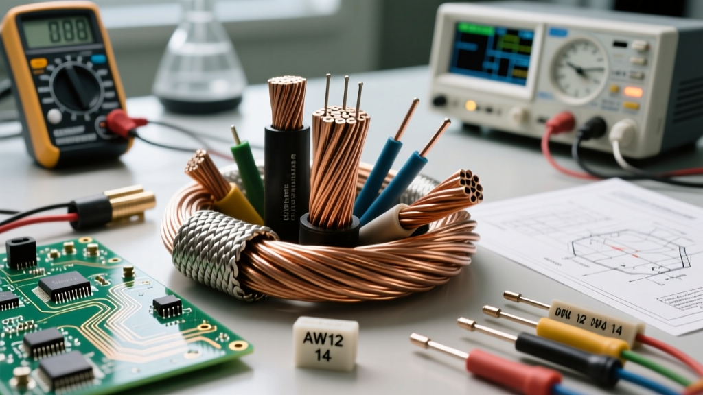
- Braided Shields (85-95% Coverage): Excellent for low-to-medium frequency AC electro-magnetic fields (60 Hz to 10 kHz). The thick copper braid provides a low-impedance path to ground for induced currents.
- Combination (Foil + Braid): Required in severe industrial environments (e.g., inside VFD enclosures) to combat both high-frequency PWM switching noise and 60 Hz inductive coupling.
Grounding Framework: To prevent ground loops—which turn the shield itself into an antenna for AC electro-magnetic noise—shields on analog signal cables should typically be grounded at the source end only. For high-frequency digital networks, 360-degree shield termination at both ends using metallic cable glands is required to maintain Faraday cage integrity.
Routing Frameworks and Conduit Selection
Physical routing dictates the severity of AC electro-magnetic coupling. Follow these structural frameworks to minimize interference and thermal derating:
- The 90-Degree Crossing Rule: When signal cables must cross high-voltage AC power lines, they must do so at a strict 90-degree angle to minimize the parallel exposure area and reduce magnetic flux linkage.
- Conduit Material Selection: Use rigid steel conduit for power lines to contain their AC electro-magnetic fields. Conversely, use non-ferrous materials (PVC, aluminum, or fiberglass) for sensitive instrumentation wiring to prevent the conduit from acting as a magnetic concentrator.
- Separation Distances: Maintain a minimum parallel separation of 12 inches between unshielded 120V/240V AC power lines and unshielded analog signal lines. If parallel routing is unavoidable, increase separation to 24 inches or use grounded steel barriers between the cable trays.
Authoritative References
- NFPA 70: National Electrical Code (NEC) - Specifically Articles 300.20 (Induced Currents) and 310.15 (Ampacity Derating).
- IEEE Std 141 (Red Book) - Power Distribution for Industrial Plants, detailing harmonic neutral sizing and proximity effects.
- Southwire Technical Resources - AC/DC resistance ratios and skin effect calculations for large gauge copper conductors.