
The Textbook Electricity Insulator Definition vs. Field Reality
If you look up a standard electricity insulator definition, you will typically find a simplistic explanation: a material that does not conduct electrical current. While this is fundamentally true for high school physics, it is dangerously incomplete for electrical engineers, DIYers, and electricians working in the real world. In practical applications, no material is a perfect insulator; every dielectric material has a breakdown threshold, a thermal limit, and specific environmental vulnerabilities.
At the atomic level, insulators are defined by their band gap. According to Georgia State University HyperPhysics, the valence electrons in an insulator are tightly bound to their parent atoms, requiring a massive energy leap (typically greater than 3 electron volts) to reach the conduction band. However, in real-world wiring, we do not just care about the atomic band gap. We care about dielectric strength, thermal degradation, UV resistance, and mechanical flexibility. Understanding these factors is the difference between a safe, long-lasting electrical installation and a catastrophic fire hazard.
Band Gap Theory in Practical Terms
In copper wire, the valence and conduction bands overlap, allowing electrons to flow freely. In materials like Polyvinyl Chloride (PVC) or Cross-Linked Polyethylene (XLPE), the wide band gap restricts electron flow. But when subjected to extreme voltage, heat, or chemical exposure, the molecular structure of the polymer can break down, effectively narrowing that band gap and allowing leakage current to flow. This is why the real-world definition of an insulator must include its operational limits.
Dielectric Strength: The True Measure of an Insulator
Dielectric strength is the maximum electric field that an insulating material can withstand before it breaks down and begins to conduct. It is typically measured in kilovolts per millimeter (kV/mm). When selecting wire for high-voltage applications or tight conduit bends, the dielectric strength of the jacket is your primary safety metric.
Below is a comparison of the dielectric breakdown voltages of common wiring insulators, based on data from The Engineering Toolbox:
| Insulating Material | Dielectric Strength (kV/mm) | Max Operating Temp (°C) | Common Application |
|---|---|---|---|
| Air (Reference) | ~3.0 | N/A | Overhead transmission lines |
| PVC (Standard) | ~14.0 - 20.0 | 70°C - 105°C | Standard residential THHN/THWN |
| PE (Polyethylene) | ~18.0 - 28.0 | 75°C | Coaxial cables, telecommunications |
| XLPE (Cross-Linked) | ~20.0 - 30.0 | 90°C | Medium/High voltage underground |
| PTFE (Teflon) | ~60.0 | 260°C | Aerospace, military, high-temp |
| Ceramic / Glass | ~10.0 - 14.0 | 1000°C+ | High-voltage substations, spark plugs |
Notice that while air is a fantastic and free insulator, it requires massive physical clearance. PTFE offers exceptional dielectric strength and thermal resilience, making it the gold standard for demanding environments, despite its high cost and stiffness.
Real-World Failure Modes: When Insulators Stop Insulating
Insulators rarely fail under normal operating conditions. Failure occurs when environmental or electrical stresses exceed the material's design parameters. Recognizing these failure modes is critical for troubleshooting and preventative maintenance.
Thermal Degradation and the PVC Meltdown
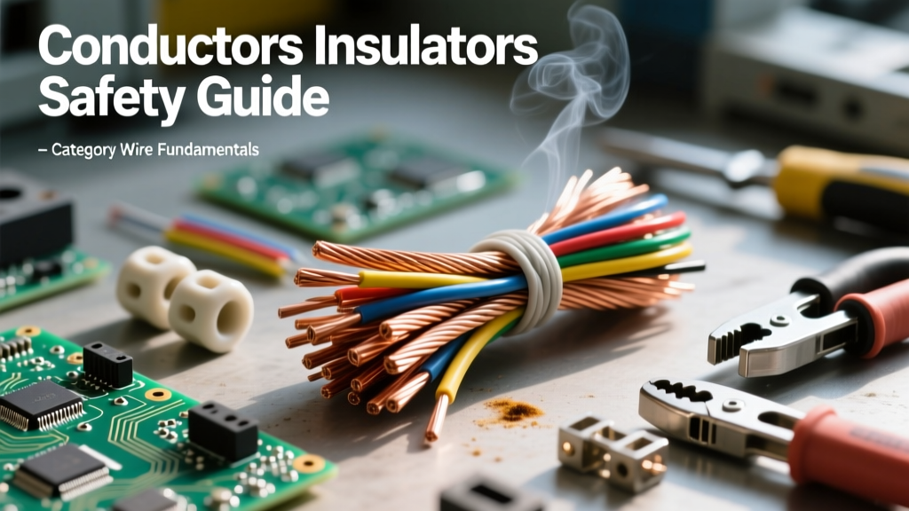
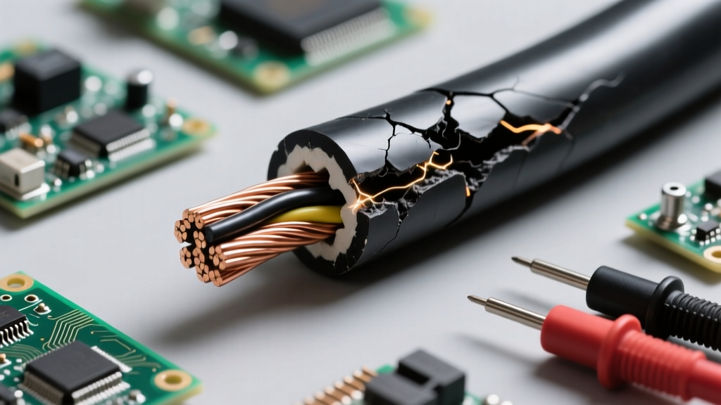
Standard PVC insulation begins to soften at around 80°C and melts or chars above 105°C. In real-world scenarios, undersized wires carrying heavy continuous loads generate excessive I²R (heat) losses. Over time, this thermal cycling causes the plasticizers in the PVC to leach out. The insulation becomes brittle, cracks when bent, and eventually exposes the bare conductor, leading to short circuits or ground faults.
Electrical Tracking and Corona Discharge
In high-voltage applications (above 2kV), the electric field around a conductor can ionize the surrounding air, creating a localized plasma known as corona discharge. This ozone-rich environment chemically attacks organic insulators like rubber and standard polymers. Furthermore, if moisture and dust settle on the surface of an insulator, a conductive path can form. This leads to electrical tracking—a phenomenon where a carbonized, permanently conductive pathway is burned into the surface of the insulating material, ultimately resulting in a flashover.
Material Selection Matrix for DIY and Pro Applications
Choosing the right insulation goes beyond matching the wire gauge. You must match the polymer chemistry to the environment.
- THHN/THWN-2 (PVC with Nylon Overcoat): The standard for indoor residential and commercial wiring. The nylon jacket provides excellent abrasion resistance for pulling through PVC or EMT conduit, but it is highly susceptible to UV degradation and should never be used for direct burial or outdoor exposed runs.
- XLPE (Cross-Linked Polyethylene): The go-to for underground feeder cables and medium-voltage utility lines. The cross-linking process creates a 3D molecular bond that prevents melting even at high temperatures, offering superior moisture and chemical resistance.
- Silicone Rubber: Highly flexible and resistant to extreme temperature swings (-50°C to +180°C). Frequently used in high-temperature appliance wiring (like ovens or kilns) and solar panel MC4 connectors where UV and weather resistance are paramount.
- EPR (Ethylene Propylene Rubber): Excellent dielectric properties and high flexibility. Often used in heavy-duty mining cables and industrial trailing cables where the wire must endure constant mechanical crushing and bending.
Troubleshooting Insulation Breakdown in Existing Circuits
Visual inspection is rarely enough to verify the integrity of an insulator. Micro-cracks and internal dielectric breakdown are invisible to the naked eye. To truly assess the health of wire insulation, professionals rely on Insulation Resistance (IR) testing using a Megohmmeter (commonly known as a Megger).
Expert Troubleshooting Tip: When testing a standard 120V/240V residential circuit, apply 500V DC from the Megohmmeter between the ungrounded (hot) conductor and the grounding conductor. A healthy PVC or XLPE insulator should read well above 1 Megohm (often in the hundreds of Megohms). If the reading drops below 1 Megohm, the insulation is compromised by moisture, thermal damage, or physical puncture, and the wire must be replaced. Never perform a Megger test on live circuits or sensitive solid-state electronics, as the high DC voltage will destroy them. (Source: Fluke Corporation)
Understanding the Polarization Index (PI)
For larger industrial motors and long cable runs, a simple spot reading isn't enough. Technicians use the Polarization Index (PI) test, which compares the IR reading at 10 minutes against the reading at 1 minute. A PI ratio of 2.0 or higher indicates clean, dry, and healthy insulation. A ratio below 1.0 suggests that the insulation is absorbing moisture or is heavily contaminated, meaning the dielectric barrier is actively failing.
Summary: Redefining the Insulator
The fundamental electricity insulator definition must evolve from a simple 'blocker of current' to a complex, engineered barrier designed to manage electrical, thermal, and mechanical stress. Whether you are selecting PTFE for a high-temperature DIY aerospace project, routing XLPE for an underground workshop feeder, or testing the PVC insulation in a 30-year-old home, understanding the specific material properties and failure modes of your insulators is the bedrock of electrical safety and reliability.