
Decoding the Sine Wave: Peak, Peak-to-Peak, and RMS
When designing circuits or sizing wire for alternating current (AC) systems, relying on simple DC math will lead to catastrophic failures, overheated conductors, and tripped breakers. Unlike direct current, which flows at a constant magnitude, AC voltage and current continuously oscillate in a sinusoidal waveform. To safely engineer AC systems, you must master the mathematical relationship between Peak, Peak-to-Peak, and Root Mean Square (RMS) values.
The most critical concept for DIY electricians and engineers is RMS (Root Mean Square). RMS represents the effective DC equivalent of an AC waveform—specifically, the amount of DC voltage that would produce the exact same heating effect in a resistive load. When you measure a standard US wall outlet with a multimeter and read 120V, you are reading the RMS voltage, not the peak.
The Core AC Voltage Formulas
- Peak Voltage (Vp): The maximum voltage reached in one direction of the sine wave.
- Peak-to-Peak Voltage (Vpp): The total voltage swing from the positive peak to the negative peak.
- RMS Voltage (Vrms): The effective working voltage.
The mathematical conversions for a pure sine wave are:
Vrms = Vp × 0.7071 (or Vp / √2)
Vp = Vrms × 1.414 (or Vrms × √2)
Vpp = 2 × Vp
For example, a standard North American 120V RMS mains supply actually reaches a peak voltage of 169.7V (120 × 1.414) and swings across a peak-to-peak range of 339.4V. This is why components like capacitors and insulation on wires must be rated for the peak voltage, not just the RMS voltage, to prevent dielectric breakdown.
Global AC Mains Parameters Chart
| Region | Nominal RMS | Peak Voltage (Vp) | Peak-to-Peak (Vpp) | Frequency | Period (T) |
|---|---|---|---|---|---|
| North America | 120V | 169.7V | 339.4V | 60 Hz | 16.67 ms |
| Europe / UK | 230V | 325.2V | 650.4V | 50 Hz | 20.00 ms |
| Japan (East) | 100V | 141.4V | 282.8V | 50 Hz | 20.00 ms |
| Australia | 230V | 325.2V | 650.4V | 50 Hz | 20.00 ms |
Frequency, Period, and Angular Velocity
Alternating current is defined by its frequency (f), measured in Hertz (Hz), which dictates how many complete cycles occur per second. The period (T) is the time it takes to complete one cycle, calculated as T = 1 / f.
In advanced AC calculations, particularly when dealing with inductors and capacitors, we use angular velocity (ω), measured in radians per second:
ω = 2πf
For a 60Hz North American grid, ω = 2 × 3.14159 × 60 = 377 rad/s. This constant (377) is fundamental when calculating reactance in AC wiring and motor windings.
The AC Power Triangle: Real, Reactive, and Apparent Power
In DC circuits, power is simply P = V × I. In AC circuits, the presence of inductive (motors, transformers) and capacitive loads causes the voltage and current waveforms to shift out of phase. This phase shift (θ) necessitates the AC Power Triangle.
1. Apparent Power (S)
Measured in Volt-Amperes (VA), this is the total power supplied to the circuit. S = Vrms × Irms. This is the value used to size transformers, generators, and main service panels.
2. Real Power (P)
Measured in Watts (W), this is the actual power doing useful work (like turning a motor shaft or generating heat). P = Vrms × Irms × cos(θ). The term cos(θ) is the Power Factor (PF).
3. Reactive Power (Q)
Measured in Volt-Amperes Reactive (VAR), this power bounces back and forth between the source and the load's magnetic/electric fields, doing no real work but still heating up the wires. Q = Vrms × Irms × sin(θ).
Calculation Example: You are wiring a 1/2 HP induction motor on a 120V circuit. The motor draws 8 Amps and has a Power Factor of 0.75.
Apparent Power: 120V × 8A = 960 VA.
Real Power: 960 VA × 0.75 = 720 Watts.
Even though the motor only consumes 720W of real power, your wiring and circuit breaker must be sized to handle the full 8 Amps (960 VA) of apparent power. Failing to account for PF leads to undersized wires and nuisance breaker trips.
Calculating Impedance (Z) in AC Circuits
Resistance (R) opposes both AC and DC equally. However, alternating current faces additional opposition from inductors and capacitors, known as Reactance (X). The total opposition in an AC circuit is called Impedance (Z), measured in Ohms (Ω).
Inductive Reactance (XL): XL = 2πfL (where L is inductance in Henries). Notice that as frequency increases, inductive reactance increases.
Capacitive Reactance (XC): XC = 1 / (2πfC) (where C is capacitance in Farads). As frequency increases, capacitive reactance decreases.
The total impedance in a series RLC circuit is calculated using vector addition, not simple arithmetic:
Z = √[R² + (XL - XC)²]
Once Z is known, you can apply Ohm's Law for AC: I = V / Z.
AC Wire Sizing: Skin Effect and Reactive Voltage Drop
Wire sizing for alternating current requires considerations beyond standard DC resistance. Two major phenomena alter how AC flows through copper and aluminum conductors: the Skin Effect and Reactive Voltage Drop.
The Skin Effect Calculation
Unlike DC, which utilizes the entire cross-section of a wire, alternating current tends to flow primarily on the outer surface (the "skin") of the conductor. This is caused by self-induced eddy currents. The depth at which the current density falls to 37% of its surface value is the Skin Depth (δ).
δ = √(ρ / (π × f × μ))
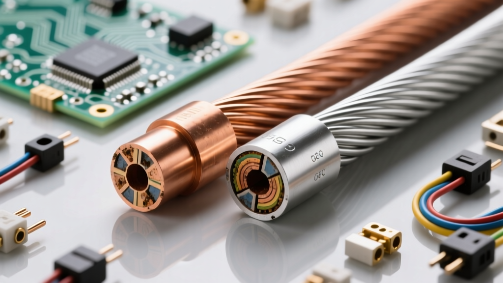
Where ρ is resistivity, f is frequency, and μ is magnetic permeability. At standard 60Hz grid frequency, the skin depth in copper is approximately 8.5 mm. For standard DIY wiring (e.g., 12 AWG or 10 AWG), the wire diameter is much smaller than the skin depth, so the effect is negligible. However, for heavy industrial feeds exceeding 1000 kcmil, the center of the conductor carries almost no current. Engineers must calculate this to avoid severe overheating, often resorting to multiple smaller parallel conductors or hollow tubing.
AC Voltage Drop Formula
In DC, voltage drop is simply V = I × R. In AC, the inductive reactance of the cable itself (especially in steel conduit) must be factored in. The exact single-phase AC voltage drop formula is:
Vdrop = 2 × I × L × (R × cos(θ) + X × sin(θ))
Where L is the one-way length, R is AC resistance per 1000ft, and X is reactance per 1000ft. If you use a standard DC calculator for a long AC run with a low power factor load (like LED drivers or fluorescent ballasts), you will underestimate the voltage drop, potentially resulting in dim lights or motor burnout.
Measurement Realities: True RMS vs. Average Responding
When verifying your calculations in the field, the tool you use matters immensely. Standard, inexpensive multimeters assume a perfect sine wave and simply multiply the average rectified voltage by 1.11 to estimate RMS. However, modern DIY projects heavily feature non-linear loads (dimmer switches, variable frequency drives, switching power supplies) that severely distort the AC waveform.
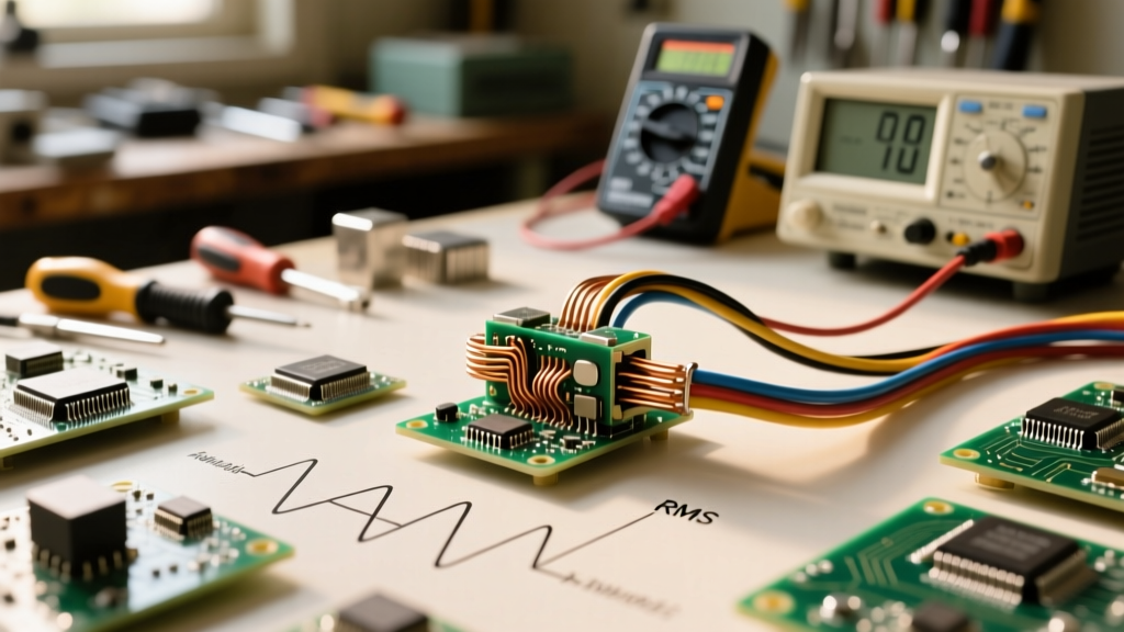
If you measure a distorted waveform with an average-responding meter, your calculations for power and wire heating will be dangerously wrong. You must use a True RMS multimeter, which samples the waveform thousands of times per second and calculates the actual heating value regardless of distortion. For a deeper dive into the mathematical foundations of AC waveforms and phase angles, the All About Circuits AC textbook provides exceptional schematic breakdowns.
Mastering these alternating current calculations ensures that your wire sizing, breaker selections, and component ratings are grounded in physical reality, keeping your electrical projects safe, efficient, and code-compliant.