
The Bosch BME280: Architecture and Capabilities
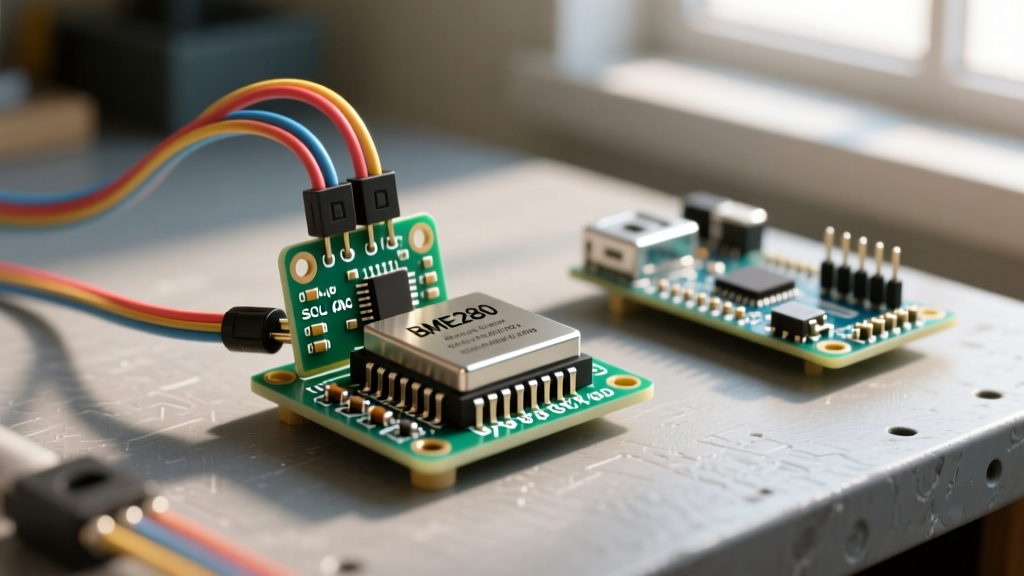
The Bosch BME280 is an industry-standard environmental sensor that integrates three distinct measurement capabilities into a single 2.5 x 2.5 x 0.93 mm LGA package: barometric pressure, temperature, and relative humidity. Unlike older generations that stacked separate dies, the BME280 utilizes a monolithic CMOS design. This integration drastically reduces the footprint and power consumption, making it a staple in ESP32 and Arduino-based weather stations, indoor air quality monitors, and drone altimeters.
At the silicon level, the sensor relies on three distinct transduction methods. The pressure sensor uses a piezo-resistive membrane that deforms under atmospheric load, altering its electrical resistance. The temperature sensor utilizes a bandgap thermal sensing circuit, while the humidity sensor employs a metal-insulator-metal (MIM) capacitive structure that absorbs ambient moisture to change its dielectric constant. According to the official Bosch Sensortec BME280 Datasheet, this architecture allows for an impressive pressure accuracy of ±1.0 hPa, which translates to roughly ±8 meters of altitude resolution.
BME280 vs. BMP280 vs. DHT22: Sensor Selection Matrix
Choosing the right environmental sensor requires balancing accuracy, interface speed, and cost. Below is a technical comparison to help you decide if the BME280 is the correct component for your PCB or breadboard prototype.
| Specification | Bosch BME280 | Bosch BMP280 | Aosong DHT22 |
|---|---|---|---|
| Parameters Measured | Temp, Humidity, Pressure | Temp, Pressure | Temp, Humidity |
| Interface | I2C (up to 3.4MHz), SPI | I2C, SPI | Single-Bus (Custom) |
| Humidity Accuracy | ±3% RH | N/A | ±2% to ±5% RH |
| Pressure Accuracy | ±1.0 hPa | ±1.0 hPa | N/A |
| Typical Market Price | $3.50 - $5.00 (Breakout) | $1.50 - $2.50 (Breakout) | $2.00 - $4.00 (Raw) |
| Read Rate (Max) | ~1.8 seconds (all 3) | ~1.0 seconds | 2.0 seconds |
Expert Warning: The Counterfeit Market
When sourcing raw ICs or unbranded breakout boards from overseas marketplaces, the BME280 is frequently counterfeited using the cheaper BMP280. Because the packages are visually identical, you must verify the silicon ID. Read theWHO_AM_Iregister at address0xD0. A genuine BME280 returns0x60, while a BMP280 returns0x58. If your code throws a "Humidity Read Error," you likely have a relabeled BMP280.
The I2C Address Dilemma: 0x76 vs 0x77
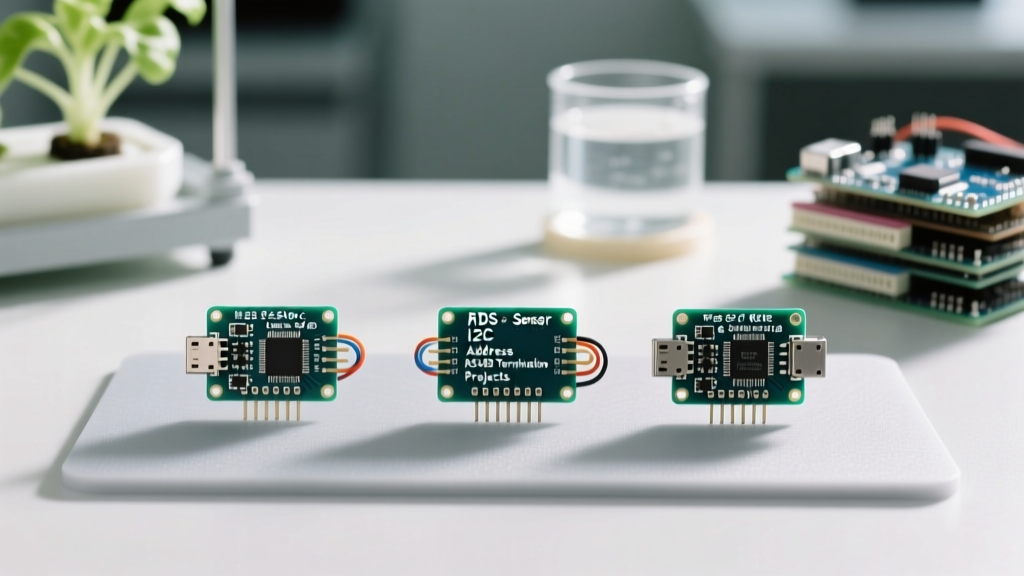
One of the most common hurdles for beginners wiring the BME280 to a microcontroller is I2C address conflicts. The BME280 supports two distinct 7-bit I2C addresses: 0x76 and 0x77. The active address is determined by the logic level of the SDO (Serial Data Out) pin.
- Address 0x76: Achieved by tying the SDO pin to GND. This is the default configuration on most Adafruit and generic breakout boards.
- Address 0x77: Achieved by tying the SDO pin to VCC (3.3V). This is the default on many SparkFun boards.
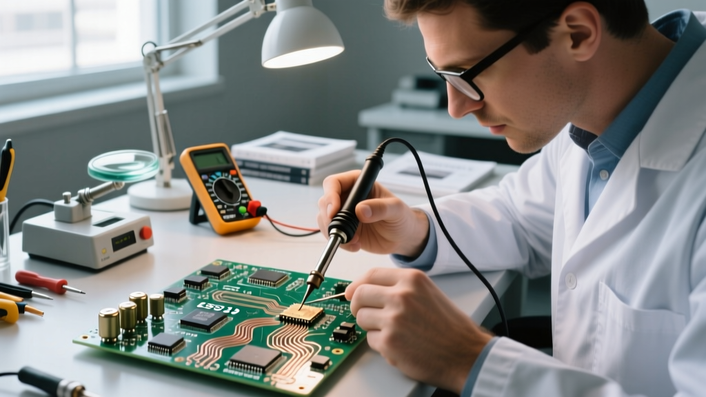
If you are building a multi-sensor array (e.g., combining an indoor BME280 with an outdoor BME280 on the same I2C bus), you must physically alter one of the breakout boards. On most PCBs, there is a small solder jumper on the back labeled "I2C ADDR". Use a soldering iron with a fine chisel tip to bridge the center pad to the VCC pad, shifting the address to 0x77 and preventing bus collisions.
Solving the BME280 Self-Heating Anomaly
A frequent complaint on electronics forums is that the BME280 reads 1.5°C to 2.5°C higher than the actual ambient room temperature. This is not a defect; it is a thermodynamic reality of the sensor's design. The BME280's internal analog-to-digital converters and logic gates generate a small amount of heat during operation. Because the sensor package is tiny and often mounted on a breakout board with copper pour, the thermal mass is low, and the silicon die heats up relative to the surrounding air.
If you configure the sensor in Normal Mode with continuous polling and zero standby time, the chip never cools down, resulting in a permanent positive temperature skew (which artificially deflates your Relative Humidity calculations).
The Professional Workaround
To achieve true ambient accuracy, you must configure the BME280 in Forced Mode or utilize a long standby time in Normal Mode. In Forced Mode, the sensor wakes up, takes a single measurement across all three domains, stores the data in the registers, and immediately returns to a low-power sleep state (drawing roughly 0.1 µA). By polling the sensor only once every 60 seconds in Forced Mode, the die has ample time to reach thermal equilibrium with the ambient air, eliminating the self-heating offset.
Advanced Configuration: Oversampling and IIR Filtering
The BME280 is not just a plug-and-play device; it features highly configurable internal DSP (Digital Signal Processing) registers. To get the most out of the Adafruit BME280 Breakout, you need to adjust the oversampling rates (osrs_t, osrs_p, osrs_h) and the IIR filter coefficient.
Oversampling reduces high-frequency noise by taking multiple internal samples and averaging them. The IIR (Infinite Impulse Response) filter smooths out sudden spikes caused by acoustic noise or wind gusts hitting the pressure membrane.
| Use Case | Temp Oversampling | Pressure Oversampling | Humidity Oversampling | IIR Filter Coeff | Standby Time |
|---|---|---|---|---|---|
| Weather Station (Static) | x1 | x1 | x1 | Off | 60s (Forced) |
| Indoor Air Quality | x2 | x16 | x1 | 16 | 0.5ms |
| Drone Altitude / Vario | x1 | x16 | Off | 4 | 0.5ms |
Notice that for drone altimeters, humidity oversampling is turned off. This saves conversion time and power, allowing the pressure sensor to update rapidly for flight controller PID loops. Conversely, an indoor air quality monitor prioritizes pressure and temperature stability using a high IIR filter to ignore the acoustic shockwave of a door slamming in the room.
Hardware Integration: Pull-Ups and Level Shifting
When wiring the BME280 to a 3.3V microcontroller like the ESP32 or Raspberry Pi Pico, the connection is straightforward: VCC to 3.3V, GND to GND, SDA to SDA, and SCL to SCL. However, integrating it into a 5V Arduino Uno or Mega environment requires strict attention to logic levels.
The BME280 is strictly a 3.3V device. Supplying 5V to the VCC pin will destroy the internal voltage regulator and fry the silicon die instantly. Furthermore, the I2C SDA and SCL pins are not 5V tolerant. If you are using a 5V microcontroller, you must use a bidirectional logic level converter (like the BSS138 MOSFET circuit) between the Arduino and the BME280.
Additionally, the I2C specification requires pull-up resistors on the SDA and SCL lines. While most premium breakout boards include 4.7kΩ or 10kΩ surface-mount pull-up resistors, cheap generic clones often omit them. If your I2C scanner returns no devices, or if the bus hangs randomly, use a multimeter to check for continuity between the SDA/SCL pins and VCC. If absent, solder two 4.7kΩ through-hole resistors from the I2C lines to the 3.3V rail. For a comprehensive breadboard wiring diagram and code examples, refer to the SparkFun BME280 Hookup Guide.
Final Calibration and Deployment Thoughts
The BME280 ships with factory-programmed calibration parameters burned into its non-volatile memory (NVM). When you initialize the sensor via a library like Adafruit's Unified Sensor library or the Bosch API, the microcontroller reads these 26 bytes of calibration data. The raw ADC readings from the sensor are mathematically compensated using these specific parameters to yield the final float values.
Never attempt to manually hardcode calibration values; every single BME280 die is laser-trimmed and calibrated individually at the Bosch factory. By understanding the sensor's thermal limitations, properly configuring the DSP registers, and respecting I2C hardware requirements, the BME280 remains one of the most reliable and data-rich environmental sensors available to the DIY electronics community.