
The Core Purpose of an RTC Module
Microcontrollers like the Arduino Uno, ESP32, and Raspberry Pi Pico are brilliant at processing logic, but they share a fundamental flaw: they possess no innate sense of time. When power is severed, their internal millisecond counters reset to zero. Furthermore, relying on internal oscillators or Wi-Fi NTP (Network Time Protocol) servers is impractical for remote, battery-powered, or offline data logging applications. This is where an RTC module (Real-Time Clock) becomes indispensable. By utilizing a dedicated 32.768 kHz crystal oscillator and a backup battery, an RTC module maintains accurate timekeeping independently of the main microcontroller's power state.
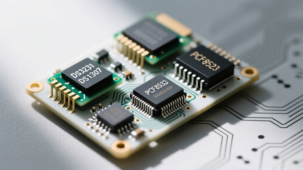
This cheat sheet serves as your definitive hardware reference for the three most ubiquitous I2C RTC chips on the market: the Maxim DS3231, the legacy DS1307, and the NXP PCF8523. Below, you will find exact I2C addresses, pinout mappings, critical power warnings, and low-level troubleshooting frameworks.
Quick-Reference Comparison Matrix
Before selecting a breakout board, review the silicon-level differences. The choice between these chips usually comes down to the trade-off between precision, power consumption, and budget.
| Chip Model | Interface | Oscillator Type | Accuracy (Typical) | I2C Address | Typical Price (Module) |
|---|---|---|---|---|---|
| DS3231 | I2C | Internal TCXO | ±2 ppm (±1 min/yr) | 0x68 | $1.50 - $4.00 |
| DS1307 | I2C | External Crystal | ±20 ppm (±10 min/yr) | 0x68 | $0.80 - $1.50 |
| PCF8523 | I2C | External Crystal | ±10 ppm | 0x68 | $2.00 - $5.00 |
| DS3234 | SPI | Internal TCXO | ±2 ppm | N/A (SPI CS) | $5.00 - $9.00 |
Hardware Pinout and I2C Addressing
Standard 4-Pin Header Mapping
Despite different silicon manufacturers, 90% of hobbyist RTC breakout boards (including the ubiquitous ZS-042 and Adafruit featherwings) standardize on a 4-pin I2C header.
- VCC: Primary power input. Connect to 5V on Arduino Uno, or 3.3V on ESP32/Raspberry Pi Pico. The DS3231 and PCF8523 handle 3.3V to 5V natively, but always verify your specific breakout board's voltage regulator.
- GND: Common ground reference.
- SDA: Serial Data Line. Connect to the hardware SDA pin of your microcontroller (e.g., A4 on Arduino Uno, GPIO 21 on ESP32).
- SCL: Serial Clock Line. Connect to the hardware SCL pin (e.g., A5 on Arduino Uno, GPIO 22 on ESP32).
Resolving I2C Address Conflicts
Notice that the DS3231, DS1307, and PCF8523 all share the exact same hardcoded I2C address: 0x68. If your project requires multiple timekeeping domains or you are prototyping on a crowded I2C bus, you cannot simply change the address via a jumper pad. To resolve this, you must use an I2C multiplexer like the TCA9548A, or isolate the secondary RTC on a separate software-defined I2C bus using bit-banging techniques.
Deep Dive: The Big Three RTC Chips
DS3231: The TCXO Precision Standard
The DS3231 is the undisputed king of DIY timekeeping. Unlike older chips that rely on an external tuning-fork crystal, the DS3231 integrates a Temperature-Compensated Crystal Oscillator (TCXO) directly inside the silicon package. It actively monitors ambient temperature and adjusts the oscillator frequency to prevent thermal drift. According to the Adafruit DS3231 Guide, this results in an accuracy of ±2 parts per million (ppm), meaning it will lose or gain less than one minute per year. Additionally, the DS3231 exposes a highly accurate onboard temperature sensor readable via registers 0x11 and 0x12.
DS1307: The Budget Legacy Option
The DS1307 is a legacy chip that requires an external 32.768 kHz crystal. Because it lacks temperature compensation, it is highly susceptible to environmental shifts. In extreme cold or heat, a DS1307 can drift by several minutes a month. Furthermore, the DS1307 requires a strict 5V logic level for reliable I2C communication, making it a poor choice for modern 3.3V microcontrollers like the ESP32 without a logic level shifter. Its only advantage is rock-bottom pricing and a built-in 56-byte NVSRAM scratchpad for storing small variables.
PCF8523: The Low-Power Alternative
Manufactured by NXP, the PCF8523 is frequently found on Adafruit and SparkFun premium boards. While it uses an external crystal, it features a built-in capacitor tuning mechanism that allows for software calibration to offset drift. Its primary advantage is ultra-low power consumption in battery backup mode, drawing mere nanoseconds of current, making it ideal for deep-sleep sensor nodes where the primary VCC is disconnected for months at a time. Consult the SparkFun RTC Hookup Guide for specific calibration register mappings.
Critical Warning: Battery Backup & Charging Circuits
The ZS-042 Charging Hazard
If you purchase a generic, unbranded DS3231 or DS1307 module online, you will likely receive the blue ZS-042 breakout board. This board features a coin cell holder on the reverse side. However, it was engineered with a primitive charging circuit—comprising a surface-mount diode (D1) and a 200Ω resistor—designed specifically for rechargeable LIR2032 lithium-ion coin cells.
SAFETY ALERT: If you insert a standard, non-rechargeable CR2032 battery into an unmodified ZS-042 module, the board will attempt to charge it. This will cause the CR2032 to overheat, swell, leak corrosive acid, and potentially rupture.
The Fix: To safely use a cheap, widely available CR2032, you must disable the charging circuit. Use a hobby knife to carefully scratch through the copper trace connecting the diode to VCC, or use a soldering iron to physically remove the surface-mount diode labeled D1. Always inspect the board under a magnifying glass before applying power.
Troubleshooting Common Failure Modes
The "1970" or "2000" Reset Bug
A frequent issue reported by beginners is the RTC resetting to January 1, 2000, or the Unix Epoch (1970) every time the microcontroller reboots. This is rarely a hardware failure. It is almost always caused by the microcontroller's setup code blindly writing a default time to the RTC registers on every boot. Ensure your code includes a conditional check: only write to the RTC if the `lostPower()` boolean flag is true, or if the current year register reads an invalid value (like 2000).
Understanding BCD (Binary-Coded Decimal)
When reading raw I2C registers from an RTC module without a library, you will encounter BCD encoding. RTC chips do not store time in standard binary. Instead, each decimal digit is stored in a separate 4-bit nibble. For example, 59 seconds is not stored as 0x3B (standard hex for 59), but rather as 0x59 (0101 1001 in binary). If your microcontroller reads 0x59 and treats it as a standard integer, your serial monitor will display "89 seconds." Always use bitwise shift operations to decode BCD, or rely on vetted libraries like the Makuna RTC Library to handle the math transparently.
I2C Bus Hanging and Pull-Up Resistors
If your I2C scanner returns no devices, or the microcontroller freezes on the Wire.endTransmission() command, your I2C bus is likely floating. Many cheap RTC modules omit the required 4.7kΩ pull-up resistors on the SDA and SCL lines to save manufacturing costs. If your microcontroller's internal pull-ups are too weak (often 20kΩ to 50kΩ), the bus will fail to reach the logic HIGH threshold. Solder a 4.7kΩ resistor between VCC and SDA, and another between VCC and SCL to stabilize the signal edges.
Leveraging the SQW Pin for Deep Sleep
For advanced low-power designs, do not ignore the SQW (Square Wave) pin. On the DS3231, this pin can be configured via the Control Register (0x0E) to output a 1Hz pulse or act as an interrupt trigger for Alarm 1 and Alarm 2. By wiring the SQW pin to a wake-up capable GPIO on an ESP32 or ATmega328P, you can put your entire microcontroller into deep sleep, allowing the RTC to consume microamps while waiting to trigger a hardware interrupt exactly when the next data reading is required. This architectural shift is the difference between a battery lasting three days and a battery lasting three years.