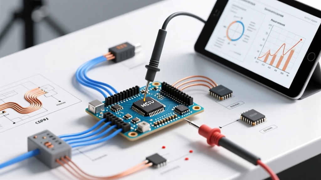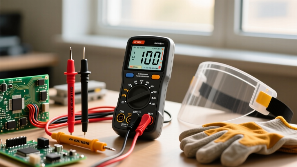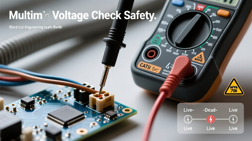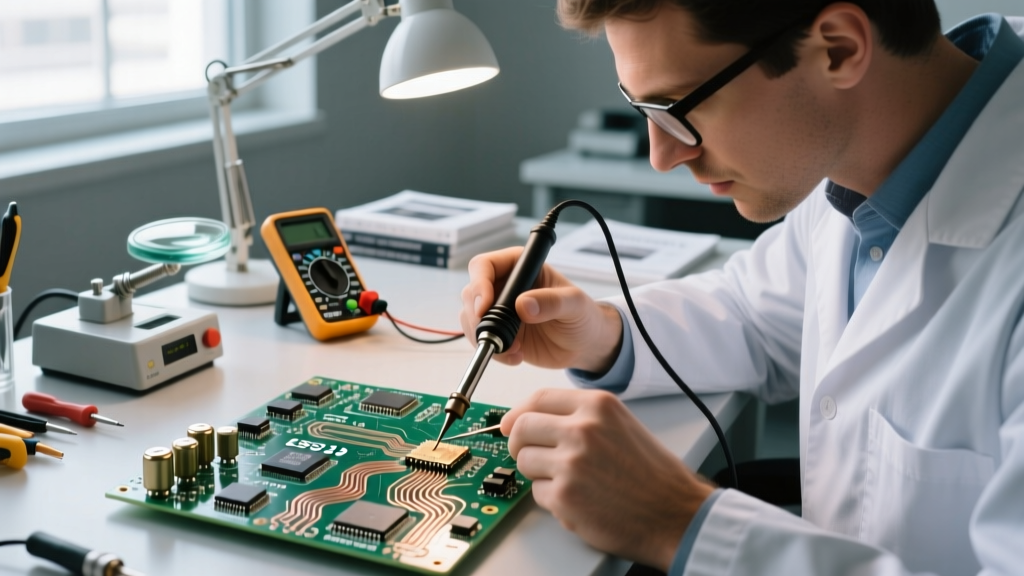

The Critical Reality of Mil-Spec Component Handling in 2026
When engineering systems for aerospace, defense, and deep-space applications, the margin for error is exactly zero. The market for military-grade electronic components USA defense contractors and aerospace engineers rely on is governed by rigorous specifications that extend far beyond the silicon itself. Procuring a MIL-PRF-38535 certified microcircuit or a radiation-hardened FPGA like the AMD (Xilinx) XQRKU060—which can easily command $25,000 to $40,000 per unit in the 2026 supply chain—is only the first step. The true challenge lies in the safe handling, storage, and assembly of these high-reliability parts.
Unlike commercial off-the-shelf (COTS) parts, mil-spec components are subjected to extreme environmental qualification. However, their robustness in operation does not equate to invulnerability on the workbench. Improper electrostatic discharge (ESD) protocols, moisture ingress, and incorrect thermal profiling during soldering can silently destroy a $30,000 component before it ever reaches the field. This guide details the exact safety, handling, and assembly best practices required to maintain the integrity of military-grade electronics.
Decoding MIL-STD Specifications and Environmental Tolerances
To handle military-grade components safely, you must first understand the testing standards they are built to survive. The foundational document is MIL-STD-883 (Test Method Standard for Microcircuits). Understanding these parameters dictates how you should treat the components prior to assembly.
| Test Parameter | MIL-STD-883 Method | Military Specification (Class S/B) | Handling Implication |
|---|---|---|---|
| Temperature Cycling | Method 1010 | -65°C to +150°C (100+ cycles) | Requires strict thermal profiling during reflow to avoid CTE shock. |
| Constant Acceleration | Method 2001 | 30,000 Gs (Y1 axis) | Internal wire bonds are robust, but ceramic package lids can fracture if dropped. |
| Fine Leak | Method 1014 | Reject limit of 5 x 10^-8 atm cc/sec | Hermetic seals are fragile; avoid mechanical stress on package pins. |
| ESD Withstand | Method 3015 | Class 2 (2,000V - 4,000V HBM) | Despite high HBM ratings, CDM (Charged Device Model) events can still destroy gates. |
Sourcing Authenticity: Defeating the Counterfeit Threat
The most severe safety risk in military electronics is not physical damage, but the integration of counterfeit or remarked components. In 2026, counterfeiters use sophisticated laser etching and X-ray-transparent epoxy to fake mil-spec markings. Installing a fake radiation-hardened part into a satellite bus guarantees catastrophic mission failure.
Verification Best Practices
- QML Certification: Only source from suppliers listed on the Defense Logistics Agency (DLA) Qualified Manufacturers List (QML) or Qualified Suppliers List of Distributors (QSLD).
- GIDEP Alerts: Regularly cross-reference part numbers and suspect vendors against the Government-Industry Data Exchange Program (GIDEP) database. GIDEP maintains active counterfeit part alerts shared across US defense contractors.
- Decapsulation and X-Ray: For high-value batches, mandate third-party testing (e.g., White Horse Laboratories). X-ray inspection must verify the internal die size and wire bond topology against the manufacturer's golden reference.
- Solderability Testing: Counterfeiters often resolder pulled parts. Mil-spec parts must pass MIL-STD-883 Method 2003 solderability testing, checking for proper wetting without evidence of prior reflow.
Expert Insight: Never accept 'new old stock' (NOS) mil-spec components from unauthorized brokers without full lot traceability back to the original manufacturer (OCM). If the original lot traveler documentation is missing, treat the batch as high-risk.
ESD and Moisture Sensitivity Handling Protocols
While military-grade ceramic packages (like CQFP, CLCC, and CPGA) are hermetically sealed and technically immune to moisture ingress, the internal die and the external support circuitry are not. Furthermore, modern mil-spec components often utilize advanced, miniaturized silicon geometries (e.g., 7nm FinFET in space-grade FPGAs) that are exquisitely sensitive to Charged Device Model (CDM) ESD events.
Implementing ANSI/ESD S20.20 in the Lab
Your facility must comply with ANSI/ESD S20.20 standards. For mil-spec handling, this requires going beyond basic commercial ESD mats:
- Continuous Monitoring: Use continuous impedance monitors on all workstations. Standard periodic wrist-strap testing is insufficient for Class S components.
- Ionization: Deploy steady-state DC ionizers above automated pick-and-place and manual inspection areas to neutralize charges on non-conductive ceramic bodies.
- Faraday Cage Storage: Store all hermetic mil-spec components in static-shielding (metallized) bags, sealed with ESD-safe tape, and placed inside conductive tote bins.
Moisture Sensitivity Level (MSL) Baking Procedures
If a mil-spec plastic-encapsulated microcircuit (PEM) is used under a MIL-PRF-38534 Class N exemption, it is subject to IPC/JEDEC J-STD-033 moisture handling rules. If the dry-pack humidity indicator card (HIC) reads >10% (indicating the desiccant is saturated), the parts must be baked before reflow to prevent the 'popcorn effect' (internal steam explosion).
- Ceramic Packages (MSL 5/6 equivalent): Bake at 125°C ±5°C for 24 hours. (Note: Ensure the specific component datasheet permits 125°C; some advanced substrates require 40°C/5% RH baking for 96 hours).
- Plastic Mil-Spec (MSL 3/4): Bake at 40°C with <5% RH for 96 to 192 hours, depending on package thickness.
Soldering and Assembly: IPC-A-610 Class 3 Standards
Assembly of military-grade electronics strictly follows IPC-A-610 Class 3 (High-Performance Electronic Products) and IPC J-STD-001 for soldering requirements. The safety and reliability of the final assembly depend on precise thermal and material control.
The Tin Whisker Problem and Leaded Solder
Unlike commercial electronics, the US defense sector maintains an exemption from the Restriction of Hazardous Substances (RoHS) directive. This is a critical safety decision. Pure tin (Sn) finishes, mandated by RoHS, are prone to growing microscopic crystalline structures known as 'tin whiskers.' These whiskers can bridge adjacent pins, causing catastrophic short circuits in high-impedance analog or high-voltage systems.
Best Practice: Always use Sn63Pb37 (63% Tin, 37% Lead) eutectic solder paste or wire for mil-spec assemblies. The addition of 37% lead effectively suppresses tin whisker growth. If the component leads are RoHS-compliant (matte tin), you must perform a hot solder dip (HSD) process to strip the pure tin and re-coat the leads in SnPb before board assembly.
Thermal Profiling for Ceramic Packages
Ceramic packages (Alumina, Al2O3) have a Coefficient of Thermal Expansion (CTE) of roughly 6.5 ppm/°C, while standard FR-4 PCBs have a CTE of 14-18 ppm/°C. This CTE mismatch creates massive shear stress on the solder joints during temperature cycling.
- Ramp Rates: Limit the reflow oven ramp-up rate to < 2°C per second to prevent thermal shock cracking in the ceramic substrate.
- Peak Temperature: For Sn63Pb37, maintain a peak temperature of 215°C - 220°C for a maximum of 60 seconds above liquidus (183°C).
- Cooling: Implement a controlled cooling ramp of -2°C to -4°C per second. Quenching the board in cold air will instantly fracture the ceramic-to-solder interface.
Conformal Coating and Environmental Protection
Once assembled, military-grade boards require conformal coating to protect against humidity, salt spray, and fungal growth (per MIL-PRF-46058 or IPC-CC-830C). However, improper coating application is a leading cause of field failures.
Application Safety and Edge Cases
- Cleanliness is Mandatory: Before coating, the assembly must undergo an aqueous or solvent wash to remove ROL0 (Rosin, Low activity, 0% halides) flux residues. Trapping ionic flux residues under a conformal coat creates a galvanic cell, leading to electrochemical migration (dendrite growth) and short circuits.
- Keep-Out Zones: Strictly mask connectors, test points, and mating surfaces. Acrylic (AR) and Urethane (UR) coatings will wick into unsealed connectors via capillary action, causing intermittent contact failures.
- Parylene Vacuum Deposition: For the highest reliability (e.g., implantable medical devices or high-altitude UAVs), use Parylene C or Parylene N. Applied via chemical vapor deposition (CVD) in a vacuum chamber, it provides a perfectly uniform, pinhole-free coating that penetrates under fine-pitch QFP leads where liquid sprays cannot reach.
Summary Checklist for Mil-Spec Assembly Safety
Before releasing any military-grade assembly to quality assurance, verify the following:
- [ ] All components traced back to OCM or verified via GIDEP.
- [ ] ESD continuous monitors active and logged per ANSI/ESD S20.20.
- [ ] MSL baking logs completed for any moisture-sensitive parts.
- [ ] Sn63Pb37 solder used; pure tin leads hot-solder dipped.
- [ ] Reflow thermal profile verified via profiling board (K-type thermocouples attached to ceramic package corners).
- [ ] Ionic cleanliness testing (ROSE or IC test) passed prior to conformal coating.
Adhering to these rigorous safety and handling protocols ensures that the inherent reliability engineered into military-grade electronic components is fully preserved through the manufacturing lifecycle. For further reading on advanced assembly workmanship, refer to the NASA Technical Standards Program, specifically NASA-STD-8739.3, which remains the gold standard for high-reliability soldering and terminal connections in the US aerospace sector.