
Beyond the Library: Why the BME280 Datasheet Matters
When integrating an environmental esp32 sensor into a DIY weather station or smart home node, the Bosch BME280 is often the default choice. It measures temperature, humidity, and barometric pressure with remarkable precision. However, most makers simply drop in the Adafruit_BME280 or SparkFun_BME280 Arduino library, call bme.begin(), and accept whatever data the serial monitor spits out.
This 'black box' approach leads to three common field failures: unexplained I2C bus lockups, massive battery drain in deep-sleep applications, and noisy pressure readings that trigger false smart-home automations. To build a truly robust node, we must bypass the abstraction layers and decode the actual Bosch BME280 Datasheet. In this guide, we will dissect the electrical characteristics, compensation registers, and power modes that dictate the real-world performance of your ESP32 sensor integration.
The ESP32 I2C Dilemma: Rise Times and Pull-Up Resistors
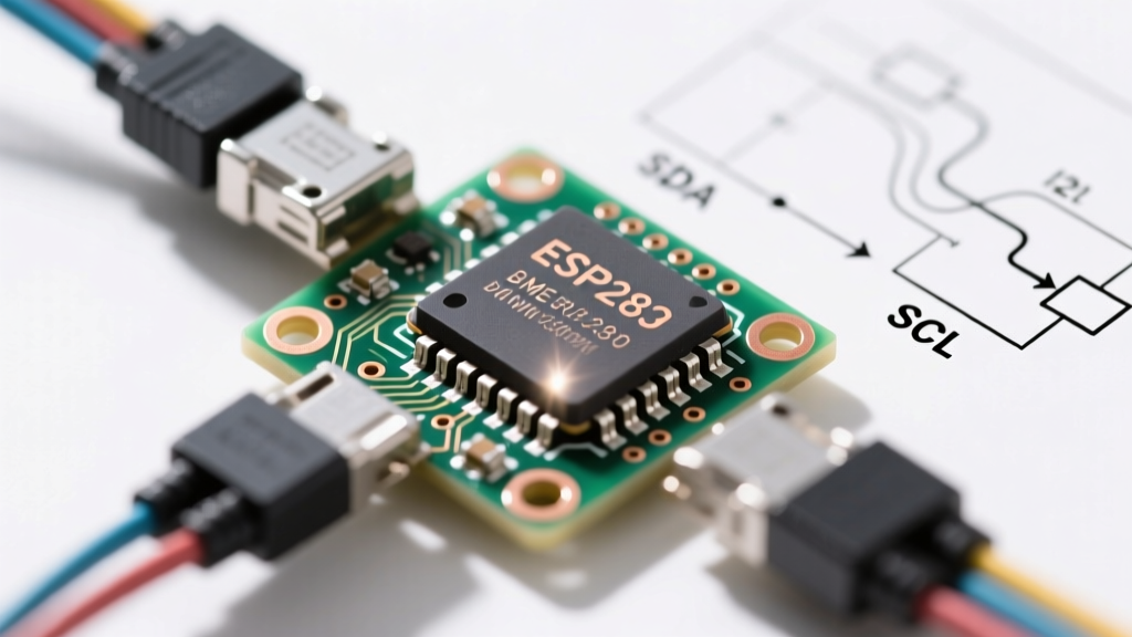
The most frequent point of failure when wiring an ESP32 sensor via I2C is ignoring bus capacitance and rise times. The ESP32’s default I2C pins (GPIO 21 for SDA, GPIO 22 for SCL) feature internal pull-up resistors. According to the ESP32 Hardware Design Guidelines, these internal pull-ups are approximately 45kΩ.
Section 5.3.3 of the BME280 datasheet specifies that for Fast Mode (400kHz) I2C at a 3.3V logic level, the maximum allowable rise time ($t_r$) is 300ns. Let us apply the standard RC time constant formula ($t_r \approx 2.2 \times R \times C$) assuming a modest bus capacitance ($C$) of 50pF (accounting for the ESP32 pin, PCB traces, and the sensor itself):
t_r = 2.2 × 45,000Ω × 50pF = 4,950ns (4.95µs)
A 4.95µs rise time catastrophically violates the 300ns limit. The ESP32 will misinterpret the sluggish voltage ramp as a logic error, leading to corrupted bytes or complete I2C bus lockups. To fix this, you must disable the internal pull-ups in software and install external resistors.
| I2C Bus Speed | Max Capacitance | Recommended Pull-Up | ESP32 Internal Pull-Up |
|---|---|---|---|
| 100 kHz (Standard) | 400 pF | 4.7kΩ | Disable (Causes marginal rise times) |
| 400 kHz (Fast) | 200 pF | 2.2kΩ or 3.3kΩ | Disable (Will cause bus failure) |
Interface Selection: The Floating CSB Pin Trap
The BME280 supports both I2C and SPI. The protocol is selected at boot by sampling the CSB (Chip Select) pin. If you are using I2C, the datasheet explicitly states that CSB must be tied to VDD (3.3V).
Datasheet Warning: If the CSB pin is left floating, the sensor's internal power-on-reset (POR) circuit may sample a random logic state due to electromagnetic interference. Your ESP32 sensor will randomly 'disappear' from the I2C bus and revert to SPI mode upon rebooting. Always hardwire CSB to 3.3V for I2C deployments.
Furthermore, the SDO pin dictates the I2C address. Tying SDO to GND yields 0x76, while tying it to VDD yields 0x77. Never leave SDO floating; the internal address register will oscillate, causing intermittent I2C_NACK errors on the ESP32.
Decoding the Calibration Registers (0x88 - 0x9F)
The raw ADC values output by the BME280 are meaningless on their own. They must be mathatically compensated using factory-programmed calibration data stored in the sensor's non-volatile memory. The ESP32 must read 32 bytes of calibration data spanning registers 0x88 to 0x9F (Temperature and Pressure) and 0xE1 to 0xE7 (Humidity).
The Endian Byte-Swapping Bug
A classic mistake when writing custom ESP32 sensor drivers is mishandling endianness. The ESP32 (Xtensa LX6 architecture) is a little-endian system. Fortunately, the BME280 also transmits its calibration words in little-endian format (LSB first, MSB second). However, parameters like dig_P4 through dig_P9 are signed 16-bit integers, while dig_P1 is an unsigned 16-bit integer.
If you cast all calibration variables as standard int16_t in your C++ struct, dig_P1 will overflow into negative numbers if the factory calibration value exceeds 32,767. This results in calculated pressure readings that are wildly inaccurate, often showing negative Pascals. Always map the exact signed/unsigned definitions from Table 18 of the datasheet to your ESP32 memory struct.
Power Profiling: Forced vs. Normal Mode
For battery-operated ESP32 sensor nodes utilizing LiPo cells and solar harvesting, power consumption is critical. The BME280 offers three primary modes: Sleep, Forced, and Normal. Most off-the-shelf libraries default to Normal mode, which continuously cycles the sensor, drawing an average of ~1mA. By leveraging the ESP32's deep-sleep capabilities alongside the BME280's Forced mode, you can drop the sensor's average current to microamps.
| Mode | Avg Current (1x OS) | Wake-up Time | Best ESP32 Use Case |
|---|---|---|---|
| Sleep | ~0.1 µA | N/A | ESP32 in shipping/storage mode |
| Forced | ~1.2 µA (1min cycle) | ~5ms | ESP32 Deep Sleep with ULP wake-up |
| Normal | ~1.0 mA | Continuous | Mains-powered HVAC thermostats |
To implement Forced mode, write 0x01 to the ctrl_meas register (0xF4) bits 1-0. The sensor takes a single measurement, stores it in the data registers, and immediately returns to Sleep mode. The ESP32 can then read the data and return to deep sleep.
Filtering Noise: The IIR Filter Coefficient
Barometric pressure is highly sensitive to acoustic noise and minor air currents (like a door closing or an HVAC vent kicking on). The BME280 datasheet details an internal Infinite Impulse Response (IIR) filter located in the config register (0xF5), bits 4-2.
Setting the IIR filter coefficient to 16 (binary 100) forces the sensor to internally average out high-frequency pressure spikes. This is vastly superior to software-based oversampling on the ESP32, as it prevents the ADC from saturating before the data is even digitized. For indoor smart home nodes, an IIR coefficient of 16 combined with a 1x oversampling rate provides the cleanest data with the lowest power penalty.
Real-World Diagnostics: Reading the Chip ID
Before attempting to configure oversampling or IIR filters, your ESP32 firmware must verify the sensor's identity. Register 0xD0 holds the Chip ID. For a genuine Bosch BME280, this value is strictly 0x60.
- Reading 0x60: I2C bus is healthy, sensor is present and responding.
- Reading 0xFF or 0x00: The I2C bus is dead. Check your external pull-up resistors and verify wiring continuity.
- Reading 0x55 or 0x58: You are likely communicating with an MPU6050 or another device on the bus due to an address collision, or you are accidentally reading the SPI MISO line while it is floating.
Final Wiring Checklist for ESP32 Sensor Integration
Integrating an environmental sensor goes far beyond copying example code. By treating the datasheet as your primary schematic, you eliminate the silent failures that plague long-term IoT deployments. Ensure you have external 2.2kΩ pull-ups for 400kHz I2C, hardwire your CSB and SDO pins to definitive logic levels, and utilize Forced mode paired with the ESP32's native deep-sleep RTC timers. Mastering these datasheet nuances is what separates a fragile breadboard prototype from a resilient, field-ready ESP32 sensor node.