
Integrating an Arduino accelerometer into your next motion-tracking, vibration-analysis, or robotics project should be a straightforward process. However, thousands of makers annually fall into the same compatibility traps: fried logic gates, I2C bus lockups, and silent FIFO buffer overflows. When your serial monitor spits out NaN or 0x00, the issue is rarely a broken sensor. It is almost always a fundamental mismatch in voltage logic, bus capacitance, or library buffer limitations.
This comprehensive compatibility guide dissects the hardware and software realities of pairing MEMS accelerometers with the Arduino ecosystem. Whether you are using a classic 5V ATmega328P-based Uno or a 3.3V ARM Cortex-M0 Nano 33 IoT, understanding the electrical boundaries of your sensor is the difference between a reliable deployment and a debugging nightmare.
The 5V vs 3.3V Logic Level Trap
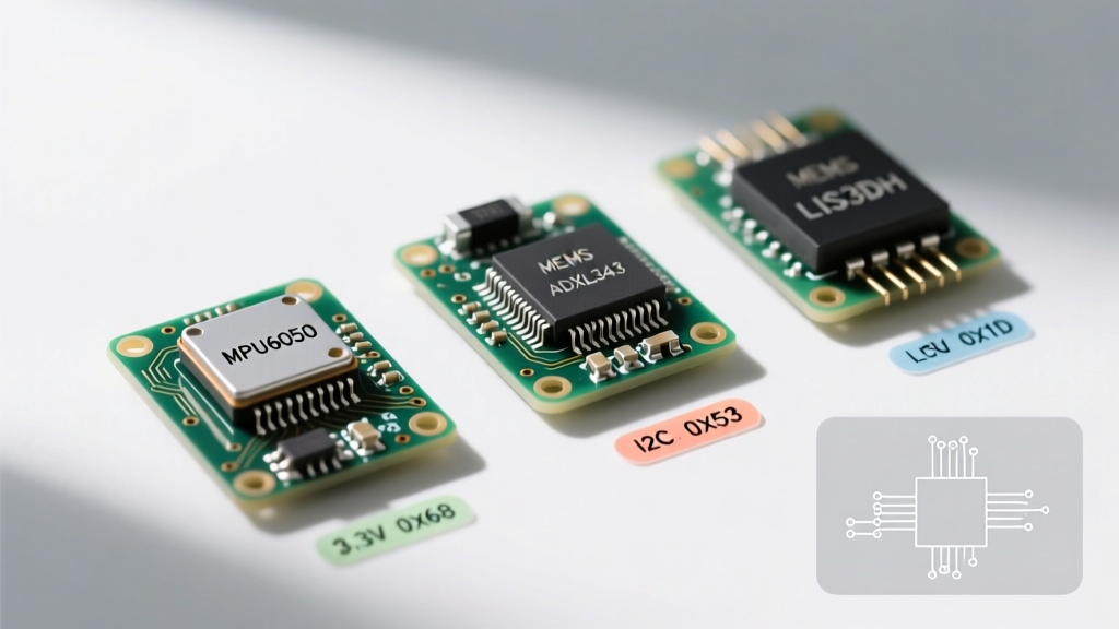
The most catastrophic failure mode in Arduino accelerometer wiring is ignoring logic level thresholds. Modern MEMS accelerometers—including the ubiquitous InvenSense MPU-6050, Analog Devices ADXL345, and STMicroelectronics LIS3DH—are strictly 3.3V devices. Their I2C and SPI data lines (SDA, SCL, MOSI, MISO) are not 5V tolerant.
If you connect a 5V Arduino Uno directly to a raw 3.3V accelerometer breakout board, the 5V logic HIGH from the ATmega328P will force current through the sensor's internal ESD protection diodes. While the sensor might function for a few hours, this continuous over-voltage stress will eventually cause thermal runaway, permanently bricking the silicon.
Breakout Board Teardowns: Clones vs. Premium
Not all breakout boards are created equal. When sourcing an Arduino accelerometer, the PCB design dictates your compatibility:
- Premium Breakouts (Adafruit, SparkFun, Pololu): These boards include onboard 3.3V LDO voltage regulators and BSS138 MOSFET-based bidirectional logic level shifters. You can safely wire their I2C pins directly to a 5V Arduino Uno. The shifters safely translate the 5V SDA/SCL signals down to 3.3V before they hit the sensor.
- Budget Clone Boards (Generic AliExpress/eBay): These $2 boards typically feature a basic 3.3V LDO (like the ME6211) to power the chip, but they lack logic level shifters. The I2C pins are tied directly to the 3.3V sensor. If you use these with a 5V Arduino, you must use an external logic level converter or operate the Arduino on a 3.3V architecture (like the Arduino Due or Nano 33 BLE).
Expert Insight: Never rely on the Arduino's 3.3V output pin to power an accelerometer if the sensor draws more than 50mA during peak transmission. The onboard 3.3V regulator on an official Arduino Uno is notoriously weak and prone to voltage sag, which will cause the accelerometer to brown-out and reset mid-sketch.
Head-to-Head Chip Compatibility Matrix
Selecting the right sensor requires matching the chip's native interface and address space with your project's constraints. Below is a compatibility matrix of the most popular Arduino accelerometer ICs available on the maker market.
| Chip Model | Interface | Default I2C Address | Logic Voltage | Best Arduino Library | Approx. Breakout Price |
|---|---|---|---|---|---|
| MPU-6050 | I2C | 0x68 (AD0=LOW) | 3.3V | Adafruit_MPU6050 | $2 - $12 |
| ADXL345 | I2C / SPI | 0x53 (SDO=LOW) | 3.3V | Adafruit_ADXL345 | $4 - $15 |
| LIS3DH | I2C / SPI | 0x18 (SA0=LOW) | 3.3V | Adafruit_LIS3DH | $5 - $10 |
| BMI270 | I2C / SPI | 0x68 (CSB=HIGH) | 3.3V | Bosch BMI270 API | $8 - $20 |
| BMA456 | I2C / SPI | 0x18 (SDO=LOW) | 3.3V | Bosch Sensor API | $6 - $14 |
Resolving I2C Address Collisions and Bus Capacitance
The I2C protocol is the default choice for most Arduino accelerometer projects due to its low pin count. However, the SparkFun I2C Tutorial highlights a critical hardware limitation: bus capacitance. The I2C specification limits total bus capacitance to 400pF. Every wire, breadboard contact, and sensor module adds parasitic capacitance to the SDA and SCL lines.
If you are wiring an MPU-6050 alongside an SSD1306 OLED display and a BME280 environmental sensor, you are likely exceeding this capacitance limit. On an oscilloscope, the sharp square waves of your I2C clock will degrade into rounded, shark-fin shapes. The accelerometer will fail to acknowledge (ACK) the Arduino's polling requests, resulting in I2C bus lockups.
The Pull-Up Resistor Solution
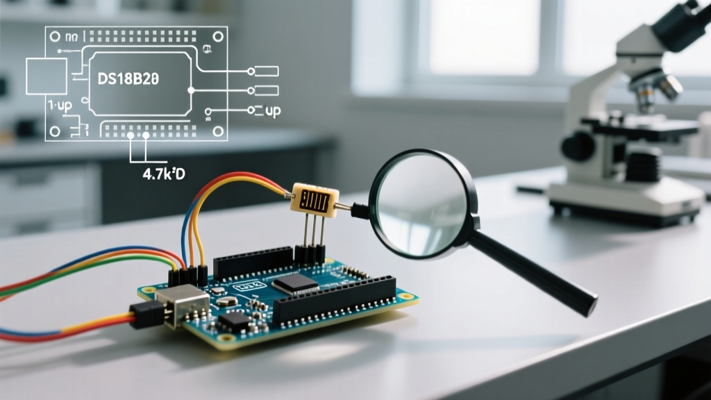
To combat high capacitance, you must lower the resistance of your I2C pull-up resistors. While 4.7kΩ is the standard default, a heavily loaded bus requires 2.2kΩ or even 1.5kΩ pull-ups to 3.3V to pull the voltage high fast enough to meet the I2C timing specifications. Note that if you are using premium breakout boards, each board likely already has 4.7kΩ pull-ups onboard. Paralleling three breakout boards yields an equivalent resistance of ~1.5kΩ, which is generally safe but pushes the current sink limits of the ATmega328P's I/O pins.
SPI Fallback: Bypassing the Wire.h Buffer Limit
When building high-speed data loggers for vibration analysis or modal testing, I2C is often too slow. The MPU-6050 and ADXL345 feature internal FIFO (First-In-First-Out) buffers that can store dozens of readings while the microcontroller handles other tasks. However, reading this FIFO over I2C on a standard AVR Arduino exposes a severe software bottleneck.
The native Arduino Wire Library utilizes a hardcoded 32-byte receive buffer on ATmega328P boards. If your accelerometer's FIFO holds 64 bytes of X, Y, and Z axis data, and you attempt a single Wire.requestFrom() call, the library will silently truncate the data at 32 bytes. Your sketch will read corrupted, misaligned axis data, leading to erratic behavior.
The SPI Advantage: Switching your Arduino accelerometer to the SPI bus eliminates the 32-byte buffer limitation. SPI allows you to stream continuous blocks of data directly into your SRAM arrays at clock speeds up to 10MHz (compared to I2C's 400kHz Fast Mode limit). When using SPI with the ADXL345, ensure your SPI settings are configured to Mode 3 (CPOL=1, CPHA=1), as the ADXL345 datasheet strictly requires this phase alignment for valid register reads.
Library Ecosystem and Board Manager Quirks
Software compatibility is just as vital as hardware wiring. The Arduino ecosystem offers two distinct paradigms for reading accelerometer data:
- Adafruit Unified Sensor API: Libraries like
Adafruit_MPU6050abstract the raw register data into standard SI units (meters per second squared, m/s²). This is highly recommended for sensor fusion algorithms like the Mahony or Madgwick filters, as it standardizes the orientation and scale across different chips. You can explore their implementation in the Adafruit MPU-6050 Guide. - Bare-Metal Register I/O: For ultra-low-power applications using the LIS3DH or BMA456, abstraction layers introduce unacceptable overhead. Writing directly to the
CTRL_REG1andFIFO_CTRL_REGregisters via raw I2C commands allows you to utilize advanced hardware features like "Wake-on-Motion" interrupts, which can drop the sensor's current draw to under 2µA while waiting for a physical tap.
Handling Interrupt Pins (INT1 / INT2)
A common compatibility oversight involves the interrupt pins. Accelerometers use these pins to signal that new data is ready or that a threshold (like a free-fall or double-tap) has been crossed. These interrupt pins output 3.3V logic HIGH. If you are using a 5V Arduino Uno, the ATmega328P requires a minimum of 3.0V to reliably register a digital HIGH on an attachInterrupt() pin. While 3.3V usually passes this threshold, noise on long wires can cause missed interrupts. For mission-critical interrupt handling on 5V boards, route the sensor's INT pin through a single N-channel MOSFET or a dedicated level shifter channel to guarantee a crisp 5V edge.
Final Compatibility Checklist
Before uploading your sketch and applying power, verify your setup against this domain-expert checklist:
- Voltage Verification: Have you confirmed if your specific breakout board has onboard logic level shifting, or are you using an external BSS138 shifter?
- Pull-Up Audit: Are your I2C pull-up resistors correctly sized (2.2kΩ - 4.7kΩ) for the total bus capacitance?
- Address Mapping: Have you run an I2C scanner sketch to ensure your accelerometer's hex address doesn't conflict with other peripherals?
- Buffer Management: If using I2C on an AVR board, are you reading the FIFO in chunks smaller than 32 bytes to prevent Wire.h truncation?
- Decoupling Capacitors: Is there a 0.1µF ceramic capacitor placed as close to the VCC and GND pins of the accelerometer as physically possible to filter high-frequency motor noise?
By respecting the electrical boundaries and software quirks of your chosen Arduino accelerometer, you transition from trial-and-error debugging to deterministic, reliable sensor integration.