
The Anatomy of a DS18B20 Failure
The DS18B20 digital temperature sensor is a staple in microcontroller projects, favored for its 1-Wire protocol and high accuracy. However, when integrating Arduino and DS18B20 setups, makers frequently encounter frozen readings, erratic fluctuations, or complete bus failures. In 2026, the market is flooded with both genuine Analog Devices (formerly Maxim Integrated) chips and cheap counterfeits, making troubleshooting more complex than a simple wiring check.
Most DS18B20 failures are not dead sensors; they are protocol timing violations, power delivery deficits, or physical layer mismatches. This guide bypasses generic advice and dives deep into the exact hardware and software failure modes of the 1-Wire bus, providing actionable diagnostics to restore your temperature logging.
Hardware Troubleshooting: Wiring and Power Modes
The physical layer of the 1-Wire bus is unforgiving. Unlike I2C or SPI, the 1-Wire protocol relies on precise microsecond timing and parasitic capacitance management. If your Arduino serial monitor outputs -127.00 or 85.00, the root cause usually lies in one of three hardware domains.
External Power vs. Parasitic Power Mode
The DS18B20 can operate in two modes: External Power (VDD connected to 3.3V/5V) or Parasitic Power (VDD tied to GND, drawing power from the data line).
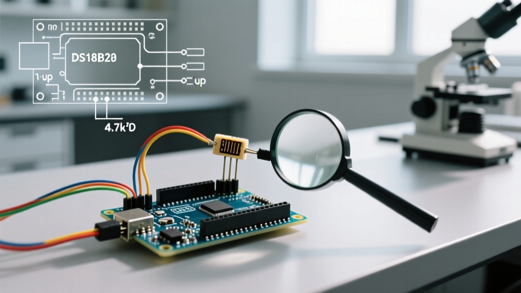
- External Power Mode: The standard and most reliable setup. Pin 1 (GND) goes to ground, Pin 2 (Data) to the Arduino digital pin, and Pin 3 (VDD) to 5V or 3.3V.
- Parasitic Power Mode: Often misunderstood. If you tie Pin 3 to GND to use parasitic power, the Arduino must provide a strong active pull-up (via a MOSFET) on the data line during the temperature conversion phase. The standard 4.7kΩ passive resistor cannot supply the 1mA required during the
CONVERT Tcommand. If you are using parasitic mode with only a passive resistor, the sensor will brown out mid-conversion, resulting in an 85°C error.
Pro-Tip: Unless you are designing a specialized 2-wire remote probe, always use External Power mode. It eliminates the need for complex active pull-up circuitry and guarantees stable conversions.
The Mandatory 4.7kΩ Pull-Up Resistor
The 1-Wire bus is an open-drain architecture. The sensor can only pull the data line LOW; it cannot drive it HIGH. A pull-up resistor between the Data line and VDD is strictly mandatory. According to the Analog Devices DS18B20 Datasheet, a 4.7kΩ resistor is standard for bus lengths under 10 meters.
If your bus has high capacitance (e.g., long Cat5e cables or multiple sensors), the RC time constant increases, causing the rising edge of the signal to slope. This violates the microsecond timing requirements of the 1-Wire protocol. Fix: Drop the pull-up resistor to 2.2kΩ or even 1.5kΩ to sharpen the rising edge on long runs.
Waterproof Probe Wire Color Chaos
If you are using a stainless steel waterproof DS18B20 probe, wire color coding is a massive source of errors. Genuine sensors and high-quality clones follow the Maxim standard, but cheap bulk imports often swap the signal and ground wires.
| Wire Color (Standard) | Function | Wire Color (Common Clone) | Function |
|---|---|---|---|
| Red | VDD (3.3V - 5V) | Red | VDD (3.3V - 5V) |
| Yellow | Data (1-Wire) | White | Data (1-Wire) |
| Black | GND | Yellow / Black | GND |
Diagnostic Step: If your Arduino resets randomly or the serial monitor outputs garbage when you plug in a waterproof probe, you likely have a VDD-to-GND short due to swapped clone wiring. Use a multimeter in continuity mode against the TO-92 pinout of a known-good bare sensor to verify your specific probe's wiring before applying power.
Decoding DS18B20 Error Values
When using the DallasTemperature Control Library, the software will return specific dummy values when the hardware layer fails. Understanding these codes saves hours of blind troubleshooting.
| Reported Value | Technical Meaning | Actionable Fix |
|---|---|---|
| 85.00 °C | Power-On Reset (POR) Scratchpad Value. The sensor is communicating, but the temperature conversion command was never executed or failed to complete. | Check for parasitic power brownouts. Increase the conversion delay in your code. Ensure the 5V rail isn't sagging during the read cycle. |
| -127.00 °C | Library-level 'Device Not Found' error. The Arduino cannot detect any ROM codes on the 1-Wire bus. | Verify the 4.7kΩ pull-up resistor. Check for broken data wires. Ensure the correct GPIO pin is defined in the OneWire constructor. |
| -196.60 °C | CRC Checksum Failure. Data was read from the sensor, but the bus noise corrupted the payload. | Lower the pull-up resistor value. Route the 1-Wire cable away from AC mains or PWM motor drivers. Add a 100nF decoupling capacitor at the sensor VDD/GND pins. |
Software and Library Diagnostics
If hardware checks out, the issue may lie in GPIO assignment or bus scanning. The PJRC OneWire Library is the underlying engine for almost all Arduino DS18B20 implementations. A common mistake is attempting to use hardware serial pins (like Pin 0 or 1 on an Uno) or SPI pins for the 1-Wire bus, causing protocol collisions.
Run this minimal bus-scanner sketch to verify if the Arduino can see the sensor's unique 64-bit ROM address. If this prints nothing, your issue is 100% hardware.
#include <OneWire.h>

OneWire oneWire(2); // Change to your specific data pin

void setup() {
  Serial.begin(115200);
  Serial.println('Scanning 1-Wire Bus...');
}

void loop() {
  byte addr[8];
  if (!oneWire.search(addr)) {
    Serial.println('No more addresses found. Check wiring and pull-up.');
    oneWire.reset_search();
    delay(2000);
    return;
  }
  Serial.print('ROM Address: ');
  for (byte i = 0; i < 8; i++) {
    Serial.print(addr[i], HEX);
    Serial.print(' ');
  }
  Serial.println();
}
Advanced Edge Cases: 3.3V Logic and Signal Integrity
As makers increasingly migrate from 5V Arduino Unos to 3.3V boards like the ESP32 or Arduino Nano 33 IoT, logic level thresholds become a critical failure point. The DS18B20 datasheet specifies that a logic HIGH must be at least 0.7 × VDD. If you power the sensor with 5V but use a 3.3V microcontroller GPIO, the 3.3V HIGH signal (3.3V / 5.0V = 0.66) falls below the 0.7 threshold. The sensor will intermittently fail to recognize the master's commands.
The Fix: Either power the DS18B20 with 3.3V (matching the MCU logic level), or use a bidirectional logic level shifter (like the BSS138 MOSFET circuit) between the 3.3V MCU and the 5V sensor bus. Alternatively, utilize an active 1-Wire master chip like the DS2482-100, which handles the strict microsecond timing and level shifting via I2C, completely offloading the protocol from the Arduino.
Genuine vs. Counterfeit DS18B20 Sensors
In the current 2026 component market, a genuine Analog Devices DS18B20+ in a TO-92 package costs between $4.50 and $6.00 from authorized distributors like Mouser or DigiKey. Conversely, multi-packs on Amazon or AliExpress often sell for under $1.00 per unit.
These cheap alternatives are frequently remarked DS18S20 chips (which have a different resolution and scratchpad layout) or factory rejects that fail to meet the ±0.5°C accuracy specification. A hallmark of a counterfeit DS18B20 is erratic behavior at temperature extremes—specifically, they often lock up or return 0x00 scratchpad data when dropped below -10°C or pushed above +85°C. If your outdoor weather station works in the spring but mysteriously fails in the winter, you are likely dealing with counterfeit silicon. Always source critical environmental monitoring components from authorized distributors.