
The Anatomy of 7-Segment Display Failures
Interfacing a 7 seg Arduino display is a rite of passage for embedded systems engineers and hobbyists alike. Whether you are building a retro-style digital clock, a custom multimeter, or an industrial sensor readout, 7-segment displays offer unparalleled readability. However, as you scale from a single digit to a multiplexed 4-digit array, hardware limitations and software timing bugs inevitably surface.
In 2026, while dedicated driver modules have largely replaced raw multiplexing for beginners, understanding the underlying physics and logic failures remains critical. A flickering digit or a dimly lit segment is rarely a defective LED; it is almost always a symptom of improper current sinking, missing blanking phases in your code, or inadequate decoupling. This guide provides a deep-dive diagnostic framework to isolate and permanently fix your display anomalies.
Symptom-to-Root-Cause Diagnostic Matrix
| Observed Symptom | Probable Root Cause | Immediate Action / Fix |
|---|---|---|
| Faint 'ghost' segments on adjacent digits | Missing blanking phase during multiplex switching | Insert delayMicroseconds(500) with all segments OFF before switching common pins. |
| Display dims as more segments turn on | Inadequate current sourcing or incorrect resistor placement | Move current-limiting resistors from common pins to individual segment pins. |
| 74HC595 shift register overheats/fails | Exceeding absolute maximum continuous current (70mA) | Recalculate resistors for 20mA/segment; use ULN2003A for common anode sinking. |
| TM1637/MAX7219 random garbage data | Signal integrity loss on CLK/DIO lines | Add 0.1µF ceramic decoupling cap across VCC/GND; check pull-up resistors. |
Fixing Multiplex Ghosting and Flicker
Ghosting occurs when a faint outline of a digit appears on an adjacent, supposedly 'off' digit. This is the most common issue in raw multiplexed 7 seg Arduino circuits. It happens because microcontroller I/O pins do not switch states instantaneously, and transistors (like the 2N2222 or BC547 used for common-pin switching) have inherent turn-off delay times.
The Physics of the Ghosting Phenomenon
Imagine your code updates Digit 1, then switches the common pin to Digit 2. If you write the new segment data for Digit 2 before Digit 1's common pin has fully deactivated, Digit 1 will briefly display Digit 2's data. Conversely, if you switch the common pin to Digit 2 before clearing Digit 1's segment data, Digit 2 will briefly display Digit 1's data.
Expert Fix: The Blanking Phase
To eliminate ghosting, you must enforce a 'blanking' phase. Turn off all segment lines, wait for the transistor to discharge (typically 100 to 500 microseconds), switch the common transistor to the next digit, wait another 100 microseconds, and then write the new segment data. This dead-time ensures zero overlap between digit states.
Flicker, on the other hand, is a software timing issue. The human eye integrates light over roughly 16 milliseconds. To achieve a flicker-free display at a 60Hz refresh rate across 4 digits, each digit must be illuminated for approximately 4ms per cycle. If your loop() contains blocking code (like delay() or heavy I2C sensor polling), the multiplexing timer interrupts will stall, resulting in a visible strobe effect. Always use hardware timers (like Timer1 via the TimerOne library) to handle multiplexing in the background via Interrupt Service Routines (ISRs).
Current Limiting: Why Your Shift Registers Keep Burning Out
A frequent and destructive mistake is placing a single current-limiting resistor on the common anode or cathode pin rather than on the individual segment lines.
The Mathematical Flaw of Common-Pin Resistors
If you place a 150Ω resistor on the common pin of a standard red 5161AS display, a single illuminated segment (like the number '1') will draw roughly 20mA. However, when you display the number '8' (all 7 segments plus the decimal point active), the total current remains constrained by that single resistor, meaning each segment receives only ~2.5mA, appearing incredibly dim.
Conversely, if you size the common resistor to provide 160mA for an '8' (approx. 18Ω), displaying a '1' will force 160mA through just two segments, instantly destroying the LED junctions or exceeding the 70mA absolute maximum rating of a Texas Instruments 74HC595 shift register, leading to thermal shutdown or silicon death.
The Correct Resistor Topology
You must place resistors on every individual segment pin (pins A through G, plus DP).
- Standard Red Displays (Vf ≈ 2.0V): With a 5V Arduino VCC, the voltage drop across the resistor is 3.0V. For a target current of 20mA:
R = 3.0V / 0.02A = 150Ω. - Blue/White Displays (Vf ≈ 3.2V): The voltage drop is only 1.8V.
R = 1.8V / 0.02A = 90Ω(Use standard 91Ω or 100Ω resistors).
Note: If driving common-anode displays with a 74HC595, remember that the HC595 is excellent at sourcing current but poor at sinking it. For high-current common-anode sinking, buffer the outputs with a ULN2003A Darlington transistor array.
Driver IC Troubleshooting: MAX7219 and TM1637
To bypass the complexities of software multiplexing, most makers in 2026 rely on dedicated driver ICs. However, these introduce their own communication-layer failures.
MAX7219 / MAX7221 SPI Anomalies
The Analog Devices MAX7219 is the gold standard for driving up to 8 digits via SPI. If your display shows random segments or fails to initialize, check the following:
- The RSET Resistor: The MAX7219 uses a single external resistor connected to pin 18 (ISET) to set the peak current for all segments. For standard red displays, a 10kΩ resistor yields roughly 20mA per segment. If your display is blindingly bright and the IC is hot, you likely used a 1kΩ resistor by mistake.
- SPI Clock Speed: The MAX7219 supports up to 10MHz. However, if you are using long, unshielded Dupont jumper wires, signal reflection will corrupt the 16-bit data packets. Drop your SPI clock speed to 1MHz or 2MHz in your Arduino sketch using
SPI.setClockDivider(SPI_CLOCK_DIV8).
TM1637 I2C-Like Protocol Glitches
The TM1637 is ubiquitous in cheap modules ($2.50 to $4.00 online) due to its 2-wire interface. Unlike true I2C, the TM1637 uses a proprietary synchronous protocol.
- Missing Pull-Ups: While many modules include 4.7kΩ pull-up resistors on the CLK and DIO lines, budget clones often omit them. If your Arduino shiftOut or custom bit-banging routines fail to register ACK bits from the TM1637, solder 4.7kΩ resistors between VCC and both data lines.
- Decoupling Capacitors: When all 4 digits display '8', the module can draw upwards of 120mA in rapid pulses. Without a local 10µF electrolytic and 0.1µF ceramic capacitor placed directly across the module's VCC and GND headers, the voltage rail will sag, causing the Arduino's brown-out detector (BOD) to reset the microcontroller.
Hardware Diagnostic Checklist
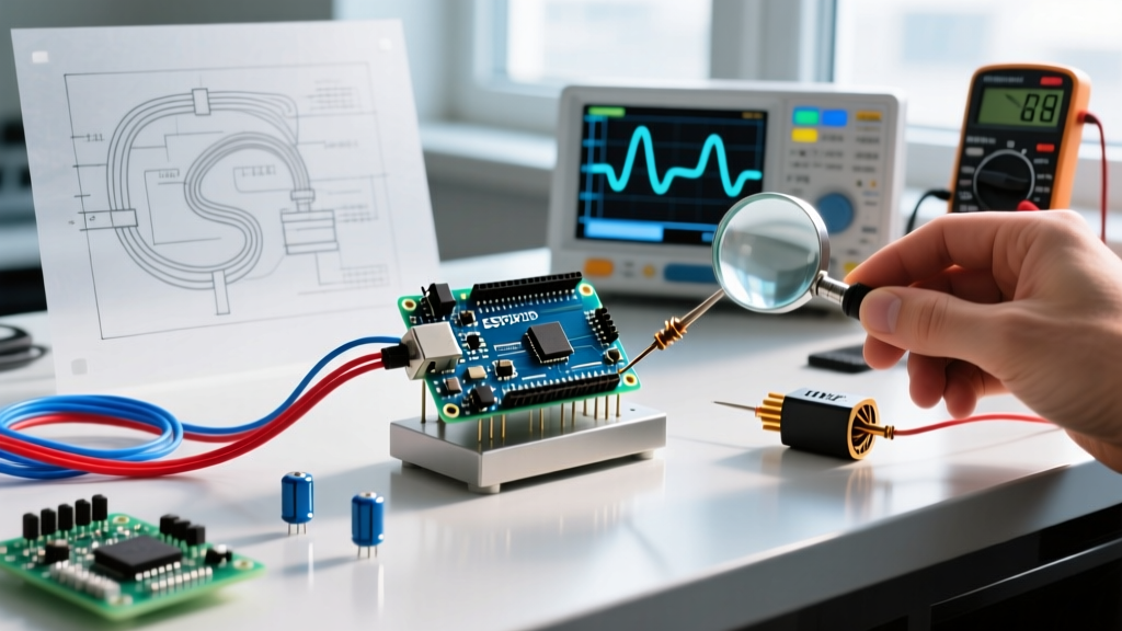
Before rewriting your firmware, verify the physical layer with a digital multimeter (DMM):
- Continuity Test: Set your DMM to diode-test mode. Place the red probe on the common pin and the black probe on segment pins (for common anode). You should read a forward voltage drop of 1.8V to 3.2V depending on the LED color. An 'OL' reading indicates a blown internal bond wire.
- Voltage Sag Measurement: Measure the 5V rail at the Arduino's 5V pin, then measure it at the display module's VCC header while displaying '8888'. A drop greater than 0.2V indicates undersized power traces or inadequate USB power delivery. Power the display from a dedicated 5V buck converter.
- Pinout Verification: Never trust the silkscreen on cheap clone boards. Always cross-reference the physical IC pin 1 indicator (the small dimple on the plastic package) with the manufacturer datasheet to ensure VCC and GND haven't been swapped on the PCB header.
Frequently Asked Questions
Can I power a 4-digit 7-segment display directly from the Arduino 5V pin?
Yes, but with strict limits. An Arduino Uno's onboard 5V linear regulator can safely supply roughly 400mA to 500mA (depending on the input voltage and thermal dissipation). A 4-digit display showing '8888' with 20mA per segment draws about 160mA. This is within limits, but if you add sensors, relays, or backlights, you will overheat the onboard regulator. Use an external 5V power supply for projects exceeding 200mA total draw.
Why does my display show inverted numbers (e.g., 6 looks like 9)?
This is a physical orientation issue, not a software bug. 7-segment displays are manufactured in various pinout configurations. If your digits appear upside down, you have likely rotated the display 180 degrees. Check the datasheet for your specific part number (e.g., 5161AS vs. 5161BS) to verify the location of Pin 1 and the common pin topology.
How do I prevent the display from showing garbage data on boot?
When an Arduino powers on or resets, its I/O pins float in a high-impedance state before the setup() function initializes them. During this boot window, floating pins can partially turn on multiplexing transistors, causing random LEDs to glow dimly. Fix this by adding 10kΩ pull-down resistors to the base of your NPN switching transistors, ensuring they remain firmly OFF until the Arduino explicitly drives them HIGH.