
Transitioning from blinking LEDs on a breadboard to making physical objects move in the real world is a massive milestone for any electronics hobbyist. Embarking on your first robot build is the ultimate test of your understanding of microcontrollers, power management, and sensor integration. While the internet is flooded with generic kits, many beginners hit a wall when their creation refuses to move, spins erratically, or constantly resets. This guide bypasses the fluff and dives deep into the electrical engineering realities of building a reliable 2WD (Two-Wheel Drive) obstacle-avoiding robot using the Arduino Uno ecosystem.
Why a 2WD Differential Chassis is the Perfect Starting Point
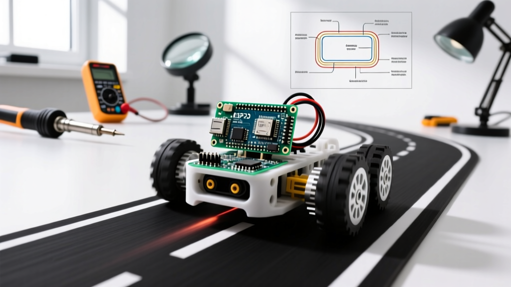
Before ordering parts, it is crucial to understand the kinematics of your platform. A 2WD differential drive system uses two independently driven wheels mounted on a single axis, with a passive caster wheel at the front or rear for balance. By varying the speed and direction of the left and right motors, you can achieve forward motion, reverse, and zero-radius tank turns.
Unlike 4WD chassis which require more complex motor drivers and suffer from binding on uneven surfaces due to the lack of a true differential gear, a 2WD setup is forgiving, power-efficient, and perfectly matched to the capabilities of entry-level motor drivers. The primary trade-off is traction; however, for indoor navigation on hard floors, the torque provided by standard TT gearmotors is more than sufficient.
The Bill of Materials (BOM) and Real-World Pricing
Sourcing the right components is where many beginner projects fail. Cheap clone motors often have mismatched gear ratios, causing the robot to pull to one side. Below is a curated BOM focusing on reliability and electrical compatibility.
| Component | Recommended Model | Est. Price | Engineering Notes |
|---|---|---|---|
| Microcontroller | Arduino Uno R3 (or high-quality clone) | $22.00 | ATmega328P provides ample I/O for basic navigation. |
| Motor Driver | L298N Dual H-Bridge Module | $6.00 | Handles up to 2A per channel. Features BJT Darlington topology. |
| Motors | TT Gearmotors (1:48 ratio, 3-6V) | $4.50 | Ensure you buy from a reputable supplier to avoid gear slippage. |
| Sensor | HC-SR04 Ultrasonic | $3.00 | 40kHz transducer. Requires 5V logic for reliable echo timing. |
| Power Source | 2x 18650 Li-Ion Cells + Holder | $15.00 | Provides 7.4V nominal. High discharge rate prevents voltage sag. |
| Chassis | Acrylic 2WD Kit with Caster | $10.00 | Pre-drilled holes for standard TT motor mounts. |
Power Supply Pitfalls: Alkaline AA vs. 18650 Li-Ion Cells
The single most common point of failure in a beginner robot build is inadequate power delivery. Most tutorials suggest using a 4xAA battery holder (6V nominal). While this works for testing motors on a desk, it fails catastrophically under real-world loads.
Standard alkaline AA batteries have a high internal resistance. When your TT motors draw their stall current (often exceeding 800mA per motor during startup or when hitting a carpet threshold), the voltage at the battery terminals sags drastically. A 6V pack can easily drop below 4V under load, causing the Arduino's onboard voltage regulator to drop out, which resets the microcontroller mid-navigation.
The Solution: Use a 2S (2-cell series) 18650 Lithium-Ion battery pack. As detailed in the Adafruit Guide to Li-Ion Batteries, a 2S pack provides a nominal 7.4V (8.4V fully charged) and can easily supply 3A+ continuous current without significant voltage sag. Furthermore, the L298N motor driver module features an onboard 7805 linear regulator. By keeping the battery voltage above 7V, you can leave the 5V enable jumper on the L298N module, safely powering both the motors and the Arduino's 5V logic rail from a single battery source.
Wiring the L298N Motor Driver and HC-SR04 Sensor
Proper wiring and grounding are non-negotiable. The L298N is an older, bipolar junction transistor (BJT) based H-bridge. According to the Texas Instruments L298 Datasheet, this topology inherently drops about 2V across the internal transistors. Therefore, an 8.4V battery input will yield roughly 6.4V at the motor terminals—perfect for 6V TT gearmotors.
Critical Pinout Mapping
- Battery Positive (7.4V) to L298N 12V terminal.
- Battery Ground to L298N GND terminal. (Crucial: You must also run a wire from this GND to the Arduino GND to establish a common logic reference).
- L298N 5V terminal to Arduino 5V pin (Bypassing the Arduino's barrel jack regulator to save heat).
- ENA / ENB (Jumpers removed) to Arduino PWM pins 5 and 6.
- IN1, IN2, IN3, IN4 to Arduino digital pins 7, 8, 9, 10.
- HC-SR04 VCC to Arduino 5V.
- HC-SR04 Trig to Arduino Pin 11.
- HC-SR04 Echo to Arduino Pin 12 (Note: HC-SR04 outputs 5V. If using a 3.3V board like an ESP32, a voltage divider is mandatory to prevent frying the GPIO).
Expert Warning: Never power DC motors directly from the Arduino's 5V or 3.3V pins. Motors generate massive Back-EMF (electromotive force) voltage spikes when they decelerate. While the L298N module includes built-in flyback diodes to protect against this, routing motor current through the microcontroller's fragile linear regulator will instantly destroy the silicon.
Core Logic: Writing the Obstacle Avoidance Sketch
The brain of your robot build relies on measuring the time it takes for a 40kHz sound wave to bounce off an object and return. The Arduino Official Documentation outlines the use of the pulseIn() function for this exact purpose.
The speed of sound in air is approximately 343 meters per second, or 0.0343 centimeters per microsecond. Because the sound wave travels to the object and back, the total distance must be divided by two. The core distance calculation in your C++ sketch should look like this:
distance = (duration * 0.0343) / 2.0;
For the avoidance logic, implement a state machine rather than using simple delay() functions. Blocking delays prevent the Arduino from reading sensor data while the robot is turning. Instead, use a non-blocking timing approach or a simple behavior-based loop: read the sensor, if the distance is less than 20cm, halt the motors, reverse for 300 milliseconds, turn right for 400 milliseconds, and resume forward motion. This creates a robust, albeit simple, navigation algorithm that prevents the robot from getting trapped in corners.
Hardware Troubleshooting: When Your Robot Spins in Circles
Even with perfect code, hardware anomalies will test your patience. Here is a diagnostic framework for the three most common issues encountered in beginner 2WD builds.
1. The Robot Veers Continuously to One Side
The Cause: Manufacturing tolerances in cheap TT gearmotors mean that applying the exact same PWM value (e.g., 200) to both ENA and ENB will rarely result in perfectly straight movement. One motor will inevitably spin 5-10% faster.
The Fix: Introduce a calibration offset in your code. Create a variable called steering_bias. If the robot pulls left, reduce the PWM value of the left motor by 10-15 points relative to the right motor until straight-line travel is achieved.
2. The HC-SR04 Returns Random '0' or '3000' Values
The Cause: Acoustic cross-talk or electrical noise. If the ultrasonic sensor is mounted too close to the chassis or the motors, the 40kHz ping can reflect off the robot's own wheels, confusing the receiver. Furthermore, the brushed DC motors generate severe electrical noise on the 5V rail.
The Fix: Solder a 100µF electrolytic capacitor directly across the VCC and GND pins of the HC-SR04 to smooth out voltage ripple caused by the motors. Additionally, set a timeout limit in your pulseIn() function to prevent the code from hanging indefinitely if an echo is never received: duration = pulseIn(echoPin, HIGH, 30000);
3. Motors Whine but Do Not Turn
The Cause: Insufficient current or a logic-level mismatch. If you are using PWM values below 80, the L298N may not have enough voltage to overcome the static friction of the TT motor gears.
The Fix: Implement a 'kickstart' routine in your code. When transitioning from a stopped state to moving, briefly send a PWM value of 255 for 50 milliseconds to break static friction, then drop down to your desired cruising speed (e.g., 150). This simple software trick drastically improves the responsiveness of high-friction budget gearmotors.
Building a 2WD obstacle avoider is more than just plugging in wires; it is an exercise in managing real-world physics, electrical noise, and mechanical tolerances. By respecting power delivery constraints and implementing software calibrations for hardware imperfections, your first robot build will transition from a frustrating desk ornament to a reliable, autonomous machine.