
Moving Beyond the Sweep Example
When engineers transition from basic pan-tilt mechanisms to complex arduino servo projects, the limitations of standard hobby PWM servos become immediately apparent. The classic Servo.h sweep example is sufficient for opening a trash can lid, but it completely fails when tasked with the precise, coordinated multi-axis movements required for a 6-Degree-of-Freedom (6-DOF) robotic arm. Advanced builds demand strict positional accuracy, real-time torque feedback, and robust power delivery architectures that standard 8-bit microcontrollers and $12 servos simply cannot provide natively.
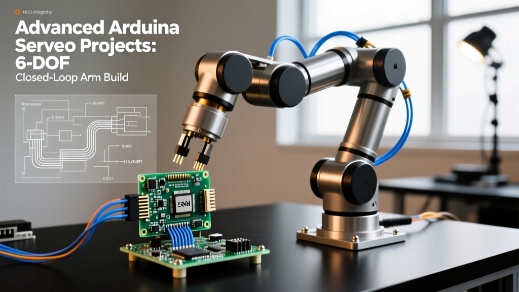
This guide dissects the engineering required to build a high-payload, closed-loop 6-DOF robotic arm using an Arduino Mega 2560 as the primary kinematics engine. We will bypass standard hardware timer conflicts, implement serial bus communication for positional feedback, and solve the catastrophic voltage sag issues that plague high-torque multi-servo arrays.
The Core Bottleneck: PWM Jitter vs. Serial Bus Feedback
Standard RC servos rely on Pulse Width Modulation (PWM) signals, typically expecting a 50Hz pulse where the high-time (usually 1ms to 2ms) dictates the target angle. This open-loop system has a fatal flaw for advanced robotics: the microcontroller has zero awareness of the servo's actual physical position, external load, or internal temperature. If the arm encounters an unexpected obstacle, a standard servo will silently stall, draw maximum current, and strip its internal plastic gears.
To achieve true closed-loop control, advanced builders are migrating to TTL serial bus servos. These servos utilize a half-duplex UART protocol, allowing the Arduino to query real-time telemetry.
| Specification | Standard PWM (MG996R) | Serial Bus (Feetech SCS15) | High-End Serial (Dynamixel XL430-W250) |
|---|---|---|---|
| Control Protocol | Analog PWM (50Hz) | TTL Half-Duplex UART (1Mbps) | TTL/RS485 Half-Duplex (up to 4.5Mbps) |
| Positional Feedback | None (Open Loop) | Yes (Potentiometer/Magnetic) | Yes (High-Res Magnetic Encoder) |
| Stall Torque (at 7.4V) | ~13 kg.cm | ~17 kg.cm | ~41 kg.cm |
| Telemetry Data | N/A | Position, Speed, Load, Voltage, Temp | Full PID state, Current, Velocity profiles |
| Approx. Unit Cost (2026) | $14.00 | $28.00 | $265.00 |
For a high-performance DIY build that balances cost and capability, the Feetech SCS15 is the current sweet spot. By querying the SCS15's internal load register, the Arduino can detect if the arm has collided with an object (indicated by a sudden spike in current draw) and immediately halt the movement sequence, preventing gear stripping and motor burnout.
Power Distribution: Solving the 40-Amp Brownout Problem
The most common point of failure in advanced multi-servo builds is inadequate power distribution. A single SCS15 servo can draw up to 2.5A under heavy load. If you command all six joints of a 6-DOF arm to move simultaneously against gravity, your instantaneous current draw can easily exceed 12A to 15A. Standard 5V linear regulators (like the L7805) or cheap breadboard power supplies will instantly thermally throttle or drop voltage, causing the Arduino Mega to brownout and reset.
Designing the Power Tree
You must separate the logic power from the actuator power. Do not attempt to power the Arduino Mega via the 5V rail of the servo bus.
- Primary Source: 7.4V 2S LiPo Battery (minimum 50C discharge rating, 2200mAh or higher).
- Actuator BEC (Battery Eliminator Circuit): A high-amperage switching buck converter. The Turnigy 8-15A UBEC or a custom LM5170-based multiphase buck board capable of sustaining 20A continuous output at 6.0V.
- Logic BEC: A separate, low-noise 5V 3A buck converter dedicated solely to the Arduino Mega and I2C sensors.
- Bulk Capacitance: Solder three 4700µF 16V Low-ESR electrolytic capacitors directly across the main servo power distribution terminals. This provides the instantaneous microsecond current spikes required when servos initialize and break static friction.
Engineering Note: Always implement a strict power-up sequence. Energize the servo logic bus first, wait 500ms for the serial bus to initialize, and then power the main actuator rail. If the high-current rail powers up simultaneously with the microcontroller, the inductive voltage drop will corrupt the Arduino's bootloader handshake.
Hardware Architecture: Bypassing Arduino Timer Conflicts
If you attempt to drive six PWM servos directly from the Arduino Mega's digital pins using the standard Arduino Servo Library Reference, you will quickly discover that the library hijacks the microcontroller's 16-bit hardware timers. This disables the analogWrite() function on specific pins and can interfere with interrupt-driven encoders or serial communication.
Furthermore, standard PWM lacks the sub-microsecond precision required for smooth, jitter-free robotic arm motion. The solution is to offload PWM generation to a dedicated I2C co-processor like the NXP PCA9685. According to the NXP PCA9685 Datasheet, this chip features a 12-bit resolution (4096 steps per cycle) and an internal 25MHz clock, completely freeing the Arduino's CPU cycles for complex kinematics calculations.
I2C Bus Integrity at Scale
When wiring the PCA9685 to the Arduino Mega, keep the I2C SDA and SCL traces under 10 centimeters. The PCA9685 operates reliably at 400kHz (Fast Mode), but at this frequency, parasitic capacitance on long wires will round off the square wave edges, leading to NACK (Not Acknowledged) errors. Always install 4.7kΩ pull-up resistors on both the SDA and SCL lines, tied directly to the clean 5V logic rail.
Inverse Kinematics (IK) Implementation on 8-Bit Silicon
Moving the end-effector (the gripper) to a specific X, Y, Z coordinate in 3D space requires Inverse Kinematics. As detailed in foundational texts like the MIT OpenCourseWare Introduction to Robotics, calculating IK involves solving complex non-linear trigonometric equations.
The Arduino Mega 2560 utilizes an 8-bit ATmega2560 AVR microcontroller. It lacks a hardware Floating Point Unit (FPU). Performing heavy matrix inversions required for Jacobian-based IK solvers will result in calculation delays of several hundred milliseconds per frame, causing the arm to move in a stuttering, low-framerate manner.
The CCD Alternative
For 8-bit architectures, implement the Cyclic Coordinate Descent (CCD) algorithm instead of Jacobian Transpose methods. CCD is an iterative, heuristic approach that rotates one joint at a time to minimize the distance to the target. It relies primarily on basic sine/cosine look-up tables and simple vector math, which the AVR chip can process in under 5 milliseconds per iteration. While CCD can occasionally result in unnatural joint configurations (like an 'elbow' pointing backward), you can constrain the joint limits in software to mimic human-like arm postures.
Real-World Troubleshooting and Edge Cases
Even with perfect code and robust power, advanced builds encounter physical layer issues. Here is how to diagnose the most common edge cases in serial bus servo arrays.
1. Serial Packet Collisions on Half-Duplex Busses
TTL serial servos share a single data wire for both transmitting and receiving. If the Arduino sends a query command while a servo is still transmitting its telemetry packet, a bus collision occurs, corrupting the data. Fix: Implement a strict master-slave polling delay. After sending a read command, the Arduino must calculate the exact byte-length of the expected return packet and delay its next transmission by at least (Packet_Length * 10) / Baud_Rate seconds, plus a 20% safety margin.
2. Ground Loop Interference
High-current switching from the servo motors injects massive amounts of electrical noise back into the ground plane. If the Arduino's logic ground and the high-current servo ground are tied together at multiple points, a ground loop forms, causing erratic I2C behavior and phantom serial bytes. Fix: Use a star-ground topology. All ground wires (Battery, BEC, Arduino, PCA9685) must meet at a single, massive copper bus bar or heavy-gauge terminal block. Never daisy-chain grounds through breadboards or thin jumper wires.
3. Thermal Throttling and Auto-Shutdown
Advanced serial servos feature internal thermal protection. If the ambient temperature inside the servo casing exceeds 85°C, the servo's internal microcontroller will cut power to the H-bridge motor driver to prevent melting. In a 6-DOF arm holding a static load, the base and shoulder servos are under constant stall torque, generating immense heat. Fix: Program a 'rest posture' routine. If the arm remains stationary for more than 30 seconds, command the servos to enter a compliant (low-torque) mode or mechanically lock the joints using external brakes, allowing the internal H-bridges to cool.
Final Calibration Protocol
Before running full IK routines, execute a low-speed calibration sweep. Command each joint to move at 10% of its maximum velocity from its minimum software limit to its maximum limit. Record the internal positional feedback values at the exact moment the physical hard-stops are reached. Map these raw serial values to your IK software's radian limits. This ensures that mathematical singularities in your code never command the servo to drive past its physical boundaries, saving your mechanical linkages from catastrophic binding.