
The Evolution of Useful Arduino Projects in 2026
The era of using microcontrollers for simple LED sequencing or basic weather stations is over. With grid export tariffs plummeting and energy costs remaining volatile in 2026, the most useful Arduino projects are those that directly interface with high-voltage infrastructure to solve real-world economic and engineering problems. Building a portfolio of advanced, utility-grade projects requires moving beyond 5V logic and into the realm of phase-angle control, inductive load management, and real-time PID feedback loops.
In this advanced build guide, we will design and engineer a Solar Surplus Energy Diverter. This device monitors your home's main electrical panel, detects when solar panels are exporting excess power to the grid, and seamlessly diverts that exact surplus into a resistive dump load (like an electric water heater) using zero-cross TRIAC switching. This prevents grid export waste and maximizes your self-consumption ROI.
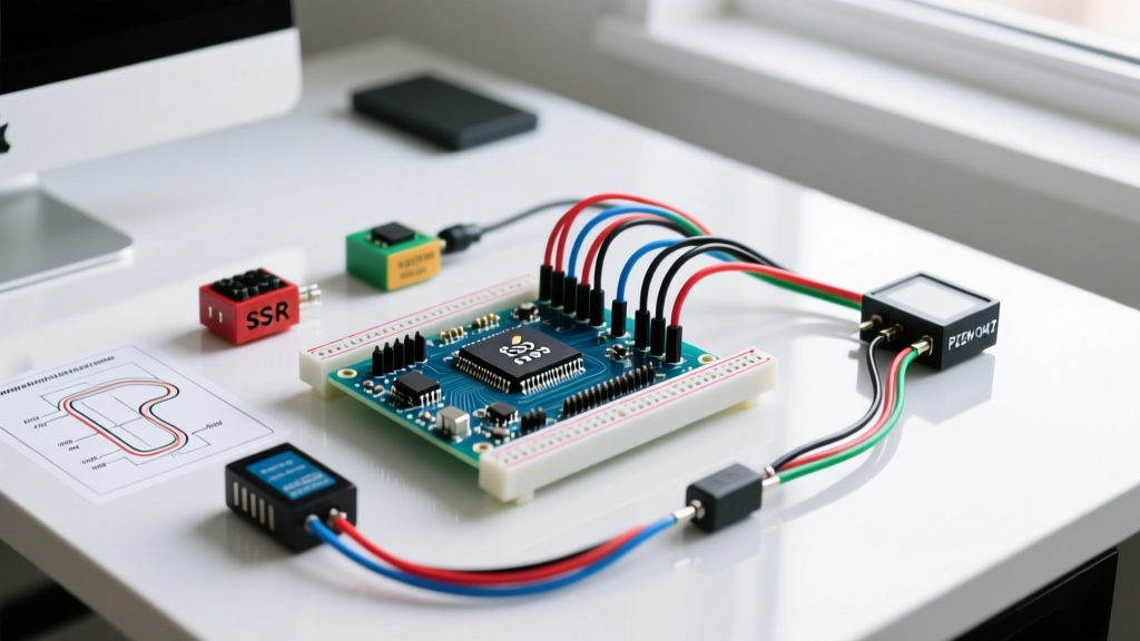
Project Blueprint & Bill of Materials (BOM)
To handle mains AC safely and process high-frequency ADC sampling, we bypass the standard Arduino Uno in favor of the Arduino Nano 33 IoT, leveraging its 3.3V logic, Cortex-M0+ processing speed, and integrated Wi-Fi for MQTT telemetry.
| Component | Model / Specification | Engineering Purpose | Est. Cost (2026) |
|---|---|---|---|
| Microcontroller | Arduino Nano 33 IoT (ABX00027) | Fast ADC, 3.3V logic, Wi-Fi telemetry | $22.00 |
| Current Sensor | YHDC SCT-013-000 (100A:50mA) | Non-invasive mains current measurement | $9.50 |
| Zero-Cross Detector | H11AA1 Optocoupler | Isolates mains AC, triggers INT0 on zero-cross | $1.20 |
| Switching Element | BTA41-600B TRIAC + MOC3021 | Phase-angle control for resistive dump load | $6.80 |
| Snubber Network | 100Ω 2W Resistor + 0.1µF X2 Cap | Suppresses dV/dt transients and EMI | $2.50 |
| Voltage Step-Down | Hi-Link HLK-PM01 (AC-DC 5V) | Isolated auxiliary power supply for MCU | $4.00 |
Total BOM Cost: ~$46.00 (excluding enclosure and PCB fabrication).
Hardware Architecture & Edge Case Mitigation
Current Transformer (CT) Burden Resistor Math
The SCT-013-000 outputs an AC current proportional to the primary mains current (100A primary = 50mA secondary). To read this with the Nano 33 IoT’s 3.3V ADC, we must convert the current to a voltage centered around a 1.65V virtual ground. According to the OpenEnergyMonitor CT sensor documentation, calculating the exact burden resistor is critical to prevent ADC clipping during peak surges.
- Peak Secondary Current: 50mA × √2 = 70.7mA
- Target Peak Voltage: 1.65V (half of 3.3V reference)
- Ideal Burden Resistor: 1.65V / 0.0707A = 23.33Ω
Edge Case Fix: Standard resistor values are 22Ω or 27Ω. We use a 22Ω 1% metal film resistor. This yields a peak voltage of 1.55V, leaving a safe 0.1V headroom to prevent ADC saturation if the grid voltage swells by 5%.
Zero-Cross Detection and Inductive Phase Shift
To control power without generating massive electromagnetic interference (EMI), the TRIAC must only switch when the AC sine wave crosses 0V. We use an H11AA1 optocoupler with anti-parallel LEDs connected directly to the mains via two 220kΩ 1W drop resistors. The transistor side pulls Arduino Pin 2 (INT0) low on every zero-crossing.
Critical Safety Warning: Never connect the Arduino ground to the mains earth or neutral. The HLK-PM01 power supply provides the necessary galvanic isolation. Always test your zero-cross detector circuit using a 12V AC transformer before connecting to 120V/240V mains.
Firmware Logic: Implementing the PID Diverter Loop
Beginner tutorials often use simple delay() functions to fire TRIACs. In advanced useful Arduino projects, blocking code is unacceptable. We use hardware interrupts and Timer1 to calculate the precise microsecond delay required to achieve a specific power output.
The Phase-Angle Calculation
For a 60Hz grid, one full half-cycle lasts 8.333ms (8333µs). If the PID controller determines we need to divert 50% of the available solar surplus, we must delay the TRIAC gate trigger by exactly 4166µs after the zero-cross interrupt fires.
void zeroCrossDetect() {
  // Detach interrupt to prevent bounce re-triggering
  detachInterrupt(digitalPinToInterrupt(ZERO_CROSS_PIN));

  // Calculate delay based on PID output (0 to 8333 uS)
  unsigned int delayTime = map(pidOutput, 0, 100, 8333, 0);

  // Set Timer1 to fire the TRIAC after 'delayTime'
  Timer1.setPeriod(delayTime);
  Timer1.attachInterrupt(fireTriac);
  Timer1.start();
}

void fireTriac() {
  digitalWrite(TRIAC_GATE_PIN, HIGH);
  delayMicroseconds(15); // Keep gate high long enough to latch
  digitalWrite(TRIAC_GATE_PIN, LOW);
  Timer1.stop();

  // Re-attach zero-cross interrupt for next cycle
  attachInterrupt(digitalPinToInterrupt(ZERO_CROSS_PIN), zeroCrossDetect, FALLING);
}
By utilizing the Arduino Nano 33 IoT hardware timers, the main loop() remains entirely free to handle Wi-Fi MQTT publishing, I2C sensor polling, and PID integral windup calculations without introducing jitter to the AC waveform.
Calibration & Real-World Troubleshooting Matrix
When transitioning from breadboard prototypes to deployed mains-voltage hardware, theoretical designs often fail due to parasitic capacitance and EMI. Below is a troubleshooting matrix derived from field-testing energy diverters in high-noise residential panels.
| Symptom | Root Cause Analysis | Engineering Fix |
|---|---|---|
| Arduino randomly resets or I2C bus locks up when TRIAC fires. | High dV/dt transients during TRIAC commutation radiating EMI into low-voltage traces. | Install an RC snubber network (100Ω + 0.1µF X2 capacitor) directly across TRIAC MT1 and MT2. Route AC and DC traces on separate PCB planes. |
| CT sensor reads 1.5A 'phantom' current when the main breaker is off. | Capacitive coupling from adjacent live wires in the electrical panel inducing voltage in the unshielded CT leads. | Use shielded twisted-pair cable for the CT sensor. Place the burden resistor and biasing network directly at the Arduino ADC pins, not at the sensor end. |
| Dump load power oscillates (hunts) wildly around the solar surplus setpoint. | Implement a 50W software deadband. If the error is less than 50W, freeze the integral term. Apply a low-pass filter (alpha = 0.2) to the raw ADC readings before feeding the PID. | |
| TRIAC fails short-circuit, dumping full mains power continuously. | Thermal runaway due to inadequate heat sinking, or voltage spike exceeding the 600V blocking rating. | Use a BTA41 (40A rating) for loads up to 3kW to provide a 50% thermal safety margin. Mount on a 15°C/W finned heatsink with thermal paste. Add a 30A fast-blow fuse in series with the load. |
Why This Redefines 'Useful' in Microcontroller Design
The transition from hobbyist to advanced embedded engineer requires a shift in perspective. Truly useful Arduino projects do not just read sensors and display data on an LCD; they close the loop and physically actuate changes in the real world safely and efficiently. By mastering zero-cross phase-angle control, calculating precise burden resistors, and mitigating mains EMI, you transform a $22 microcontroller into a commercial-grade energy management system capable of saving hundreds of dollars annually while reducing grid strain.
For further reading on AC power theory and advanced monitoring, refer to the U.S. Department of Energy's Solar Technologies Office for up-to-date statistics on residential solar self-consumption optimization strategies in 2026. Building this diverter is not just an academic exercise; it is a direct, high-ROI intervention in your home's energy infrastructure.