
Understanding Electrical Outlet Switches in Modern Wiring
When homeowners and DIYers search for electrical outlet switches, they are typically referring to one of two distinct wiring scenarios: the switch/outlet combo device (a single-gang device featuring both a toggle switch and a duplex receptacle) or the half-hot (switched) receptacle (where a standard duplex outlet is controlled by a remote wall switch). As we navigate the 2026 residential electrical landscape, understanding the precise wiring methods, National Electrical Code (NEC) requirements, and physical limitations of these devices is critical for safety and compliance.
According to the U.S. Consumer Product Safety Commission (CPSC), improper wiring of switched receptacles and combo devices remains a leading cause of residential electrical arcing and fires. This guide provides deep, actionable instructions for both scenarios, including specific torque values, box fill calculations, and product recommendations.
Scenario 1: Wiring a Switch/Outlet Combo Device
Combo devices, such as the Leviton 5245-W or the Eaton TR7745 (Tamper-Resistant), are lifesavers in retrofit situations where you need to add a switch to control a light fixture, but only have a single-gang box with an existing receptacle. They are commonly used in kitchen islands, bathroom additions, and garage workbenches.
Configuration A: Switch Controls a Separate Light Fixture
In this scenario, the receptacle remains constantly hot, while the switch controls an overhead light or exhaust fan. This requires a constant hot feed, a neutral, a ground, and a switch leg (the wire running to the light).
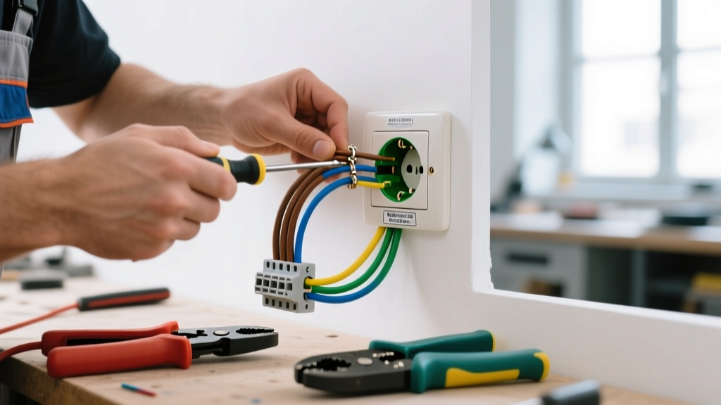
- Prepare the Wires: Strip exactly 3/4 inch of insulation from your 14 AWG or 12 AWG solid copper wires. Do not over-strip; exposed copper outside the terminal invites arcing.
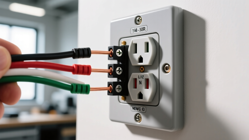
- Identify Terminals: On a standard Leviton combo device, you will see a Brass screw (hot in), a second Brass screw (switch leg out), a Silver screw (neutral), and a Green screw (ground).
- Wire the Receptacle: Connect the incoming constant hot (black) wire to the Brass screw labeled 'HOT'. Connect the incoming neutral (white) wire to the Silver screw.
- Wire the Switch: Connect the switch leg (usually a black or red wire running to the light fixture) to the second Brass screw on the switch side.
- Grounding: Connect the bare copper or green ground wire to the Green terminal. Torque to 14 in-lbs.
Configuration B: Switch Controls the Receptacle Itself
If you want the built-in switch to turn the bottom or top half of the combo receptacle on and off (useful for a workbench tool), you must use the internal jumper or 'fin' on the device. Note: Most modern combo devices do not have a breakable fin like standard duplex receptacles; they are internally wired to allow the switch to control a separate load only. Always check the manufacturer's wiring diagram on the back of the device.
Scenario 2: The Half-Hot (Switched) Standard Receptacle
The half-hot receptacle is the standard for living rooms and bedrooms, allowing a wall switch to control a lamp plugged into the top half of the outlet, while the bottom half remains constantly hot for vacuums or phone chargers.
Required Materials and Cable
Unlike a combo device, a half-hot setup requires a 3-wire cable (e.g., 14/3 NM-B or 12/3 NM-B Romex) running from the switch to the receptacle. The extra wire (usually red) acts as the switched hot return.
- White Wire: Neutral (shared)
- Black Wire: Constant Hot (from breaker to switch, or pigtailed at the receptacle)
- Red Wire: Switched Hot (from switch to the top half of the receptacle)
- Bare Copper: Equipment Ground
Step-by-Step Wiring Procedure
- Break the Hot Tab: Using needle-nose pliers, snap off the small brass connecting fin on the hot (brass) side of the duplex receptacle. This isolates the top and bottom outlets.
- Leave the Neutral Tab Intact: Never break the silver neutral tab unless you are wiring a multi-wire branch circuit (MWBC).
- Connect the Switched Hot: Attach the Red wire (coming from the wall switch) to the top Brass screw.
- Connect the Constant Hot: Attach the Black wire (constant feed) to the bottom Brass screw.
- Connect Neutral and Ground: Attach the White wire to either Silver screw, and the bare ground to the Green screw.
Expert Warning: Backstabbing (pushing wires into the quick-insert holes on the back of the device) is a primary cause of high-resistance connections and melted receptacles. The Occupational Safety and Health Administration (OSHA) and industry best practices dictate that you always use the side terminal screws, wrapping the wire clockwise around the screw so that tightening the screw pulls the loop closed.
Comparison Matrix: Combo Device vs. Half-Hot Receptacle
| Feature | Switch/Outlet Combo Device | Standard Half-Hot Receptacle |
|---|---|---|
| Typical Device Cost (2026) | $5.50 - $9.00 | $1.50 - $3.50 (TR rated) |
| Box Fill Impact (NEC 314.16) | Counts as 2 devices (4 wire allowances) | Counts as 1 device (2 wire allowances) |
| Required Wiring Cable | Standard 14/2 or 12/2 NM-B (usually) | Requires 14/3 or 12/3 NM-B |
| Primary Use Case | Kitchen islands, bathroom fan/light combos | Living room lamps, bedroom switched outlets |
| Tamper-Resistant (TR) Options | Limited (e.g., Eaton TR7745) | Widely available from all major brands |
Crucial Code Compliance and Box Fill Calculations
When installing electrical outlet switches, you must adhere to the National Fire Protection Association (NFPA) guidelines outlined in the NEC. Two specific areas trip up even experienced DIYers:
1. Tamper-Resistant (TR) Requirements
Under NEC Article 406.12, all 15A and 20A, 125V and 250V receptacles installed in dwelling units must be tamper-resistant. If you are installing a combo device in a living space, you must source a TR-rated combo device (look for the 'TR' stamped on the face and the internal shutters visible in the slots). Standard non-TR combo devices are now strictly limited to industrial or inaccessible commercial applications.
2. Box Fill Limits (NEC Article 314.16)
A common failure mode in combo device installation is cramming too many wires into a standard 18-cubic-inch single-gang box. Because a combo device contains both a switch and a receptacle, the NEC requires you to count it as two devices for box fill calculations.
- 14 AWG Wire: Each wire counts as 2.0 cubic inches. The device counts as 4.0 cubic inches (2 x 2.0).
- 12 AWG Wire: Each wire counts as 2.25 cubic inches. The device counts as 4.5 cubic inches (2 x 2.25).
If your box fill calculation exceeds the stamped volume of your electrical box, you must upgrade to a deep single-gang box (22.5 cu in) or a 4-inch square box with a single-gang mud ring.
GFCI and AFCI Considerations for Switched Outlets
In 2026, Arc-Fault Circuit Interrupter (AFCI) protection is mandatory for nearly all living areas, and Ground-Fault Circuit Interrupter (GFCI) protection is required in kitchens, bathrooms, garages, and outdoor areas.
The Edge Case: You cannot easily purchase a GFCI-protected combo switch/outlet device. If your local code requires GFCI protection for a kitchen island combo device, you have two options:
- Install a GFCI receptacle upstream in the same circuit and wire the combo device to the LOAD terminals of the GFCI.
- Use a dual-function (CAFCI/GFCI) circuit breaker in your main panel to protect the entire branch circuit.
For half-hot receptacles in living rooms, the entire circuit must be protected by an AFCI breaker at the panel. The physical receptacle on the wall does not need to be an AFCI receptacle, provided the breaker handles the protection.
Troubleshooting Common Wiring Failures
If your newly wired electrical outlet switches are malfunctioning, check these specific failure modes:
- Switch works, but outlet is dead: You likely forgot to connect the constant hot pigtail to the receptacle's brass screw, or you accidentally broke the neutral tab instead of the hot tab.
- Breaker trips immediately upon turning on the switch: You have a dead short. This usually happens if the bare copper ground wire is touching the brass switch terminal, or if the switch leg is incorrectly tied to the neutral bundle.
- Dimmer switch compatibility: Never wire a standard dimmer switch to control a half-hot receptacle unless the receptacle is strictly dedicated to dimmable LED lighting. Plugging a vacuum cleaner or phone charger into a dimmer-controlled outlet will destroy the device's power supply and create a severe fire hazard.
Final Thoughts
Wiring electrical outlet switches requires meticulous attention to terminal identification, tab-breaking mechanics, and box fill mathematics. Whether you are dropping in a Leviton combo device to save space or running 14/3 Romex for a living room half-hot setup, always verify your connections with a non-contact voltage tester and a digital multimeter before energizing the circuit. When in doubt, consult a licensed electrician to ensure your 2026 home electrical system remains safe, efficient, and fully code-compliant.